Accessible indirect entry cable gland

a technology of entry cable and indirect entry, which is applied in the direction of cable termination, cable inlet sealing means, electrical equipment, etc., can solve the problems of inability to reuse entry cable glands, external terminal boxes that require additional space, and high cost of entry cable glands

Inactive Publication Date: 2012-11-22
SANY HEAVY EQUIP
View PDF7 Cites 15 Cited by
  • Summary
  • Abstract
  • Description
  • Claims
  • Application Information

AI Technical Summary

Benefits of technology

[0007]Further, the accessible indirect entry cable gland has an o-ring positioned adjacent to the first end of the cap and gripping a jacket of the electrical cable; and a clamp adapted for mating with the first end of the cap so that the clamp and the cap can be fastened and re-fastened together after being un-fastened, where, when the clamp and the cap are fastened together, the clamp exerts a pressure on the o-ring against the jacket of the cable having one or more electrical conductors, thereby to retain the cable having one or more electrical conductors against movement with respect to the accessible indirect entry cable gland.
[0013]In another aspect, the present invention relates to an accessible indirect entry cable gland for permitting a cable having one or more electrical conductors to enter a flameproof enclosure. In one embodiment, the accessible indirect entry cable gland includes a collar having a first end and an opposite, second end, and a first bore adapted for receiving the cable from the first end thereof and passing the one or more electrical conductors through the second end thereof into the flameproof enclosure; a flame-resistant bushing filling a first part of the first bore of the collar at the second end thereof and adapted for passing the one or more electrical conductors therethrough and holding the conductors in place; a cap having a first end and an opposite, second end, and a second bore adapted for receiving the cable from the first end thereof and passing the conductors through the second end thereof into the collar, where the second end of the cap is adapted for mating with the first end of the collar so that the cap and the collar can be fastened and re-fastened together after being un-fastened, wherein, when the cap and the collar are fastened together, the second bore of the cap and a second part of the first bore of the collar at the first end thereof form a terminal chamber, and wherein the terminal chamber is accessible when the cap and the collar are un-fastened; an o-ring positioned adjacent to the first end of the cap and gripping a jacket of the cable; and a clamp adapted for mating with the first end of the cap so that the clamp and the cap can be fastened and re-fastened together after being un-fastened, where, when the clamp and cap are fastened together, the clamp exerts a pressure on the o-ring against the jacket of the cable, thereby to retain the cable against movement with respect to the accessible indirect entry cable gland.

Problems solved by technology

A flameproof enclosure is constructed so that it will contain an explosion of flammable gas or vapor and will not permit ignition of a surrounding explosive atmosphere.
This type of entry cable gland is costly and the external terminal box requires additional space.
This type of entry cable gland cannot be re-used after each repair.
Therefore, this is a costly approach throughout the lifecycle of the equipment, since the cable gland assembly needs to be replaced whenever a repair is needed.
Therefore, a heretofore unaddressed need exists in the art to address the aforementioned deficiencies and inadequacies.

Method used


Image

  • Accessible indirect entry cable gland
  • Accessible indirect entry cable gland
  • Accessible indirect entry cable gland

Examples


Embodiment Construction

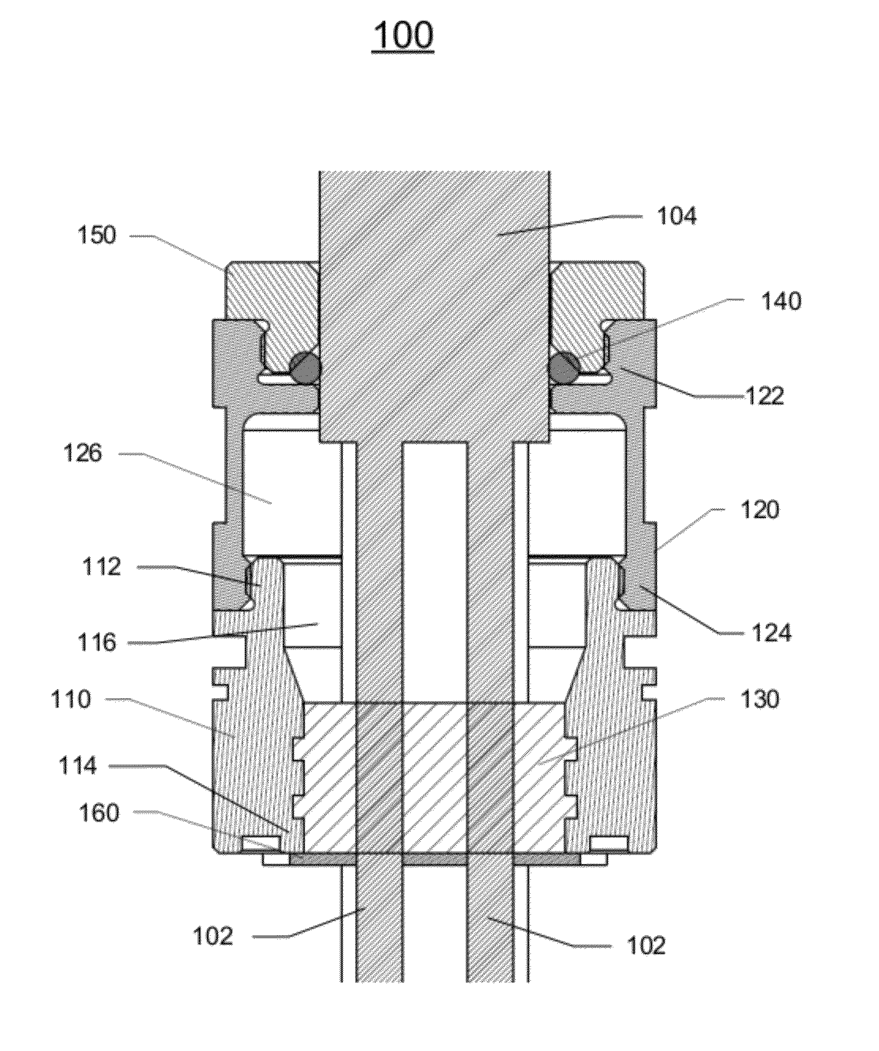
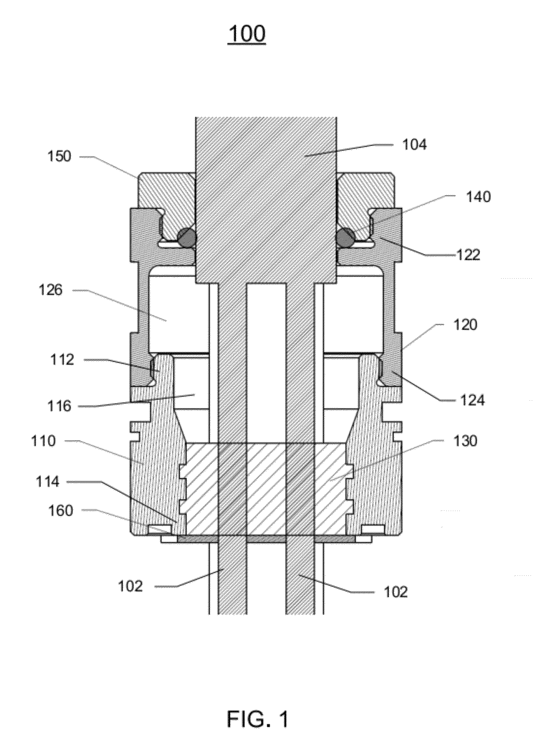
[0023]The present invention will now be described more fully hereinafter with reference to the accompanying drawings, in which exemplary embodiments of the invention are shown. This invention may, however, be embodied in many different forms and should not be construed as limited to the embodiments set forth herein. Rather, these embodiments are provided so that this disclosure will be thorough and complete, and will fully convey the scope of the invention to those skilled in the art. Like reference numerals refer to like elements throughout.

[0024]It will be understood that when an element is referred to as being “on” another element, it can be directly on the other element or intervening elements may be present therebetween. In contrast, when an element is referred to as being “directly on” another element, there are no intervening elements present. As used herein, the term “and / or” includes any and all combinations of one or more of the associated listed items.

[0025]It will be und...


PUM


Abstract

In one aspect of the present invention, an accessible indirect entry cable gland has a collar having a first end, an opposite, second end, and a first bore adapted for receiving a cable having one or more electrical conductors from the first end thereof and passing the cable through the second end thereof into a flameproof enclosure, a flame-resistant bushing filling a first part of the first bore of the collar at the second end thereof and adapted for passing the cable therethrough and holding the cable in place, and a cap having a first end and an opposite, second end, and a second bore adapted for receiving the cable from the first end thereof and passing the cable having one or more electrical conductors through the second end thereof into the collar. The accessible indirect entry cable gland further has an o-ring positioned adjacent to the first end of the cap and gripping a jacket of the cable, and a clamp adapted for mating with the first end of the cap so that the clamp and the cap can be fastened and re-fastened together after being un-fastened, wherein, when the clamp and the cap are fastened together, the clamp exerts a pressure on the o-ring against the jacket of the cable, thereby to retain the cable against movement with respect to the accessible indirect entry cable gland.

Description

FIELD OF THE INVENTION[0001]The present invention relates to a cable gland, and more particularly, to an accessible indirect entry cable gland that has an accessible terminal chamber for permitting a cable having one or more electrical conductors to enter a flameproof enclosure, where the accessible terminal chamber is filled with a flame-resistant compound for keeping the one or more electrical conductors of the cable separated.BACKGROUND OF THE INVENTION[0002]A flameproof enclosure is used when electrical components, such as switches and contactors, may cause sparks or arcing in normal operation conditions. A flameproof enclosure is constructed so that it will contain an explosion of flammable gas or vapor and will not permit ignition of a surrounding explosive atmosphere. Flameproof enclosures are widely used in mining equipment and other types of equipment used in hazardous environments. Electrical cables can be brought into a flameproof enclosure directly or indirectly. In the ...

Claims


Application Information

Patent Timeline
Patent Type & Authority Applications(United States)
IPC IPC(8): H02G3/18
CPCH02G3/22H02G15/04H02G15/013
Inventor THOMAS, DAVID G.
Owner SANY HEAVY EQUIP
Why Eureka
Try Eureka