Indirect entry cable gland assembly

A technology of cable clamps and components, which is applied in the field of indirect lead-in cable jacket components, and can solve the problem of high cost

Inactive Publication Date: 2007-08-29
JOY MM DELAWARE INC
View PDF1 Cites 7 Cited by
  • Summary
  • Abstract
  • Description
  • Claims
  • Application Information

AI Technical Summary

Problems solved by technology

This is an extremely costly way to achieve indirect introductions

Method used


Image

  • Indirect entry cable gland assembly
  • Indirect entry cable gland assembly

Examples


Embodiment Construction

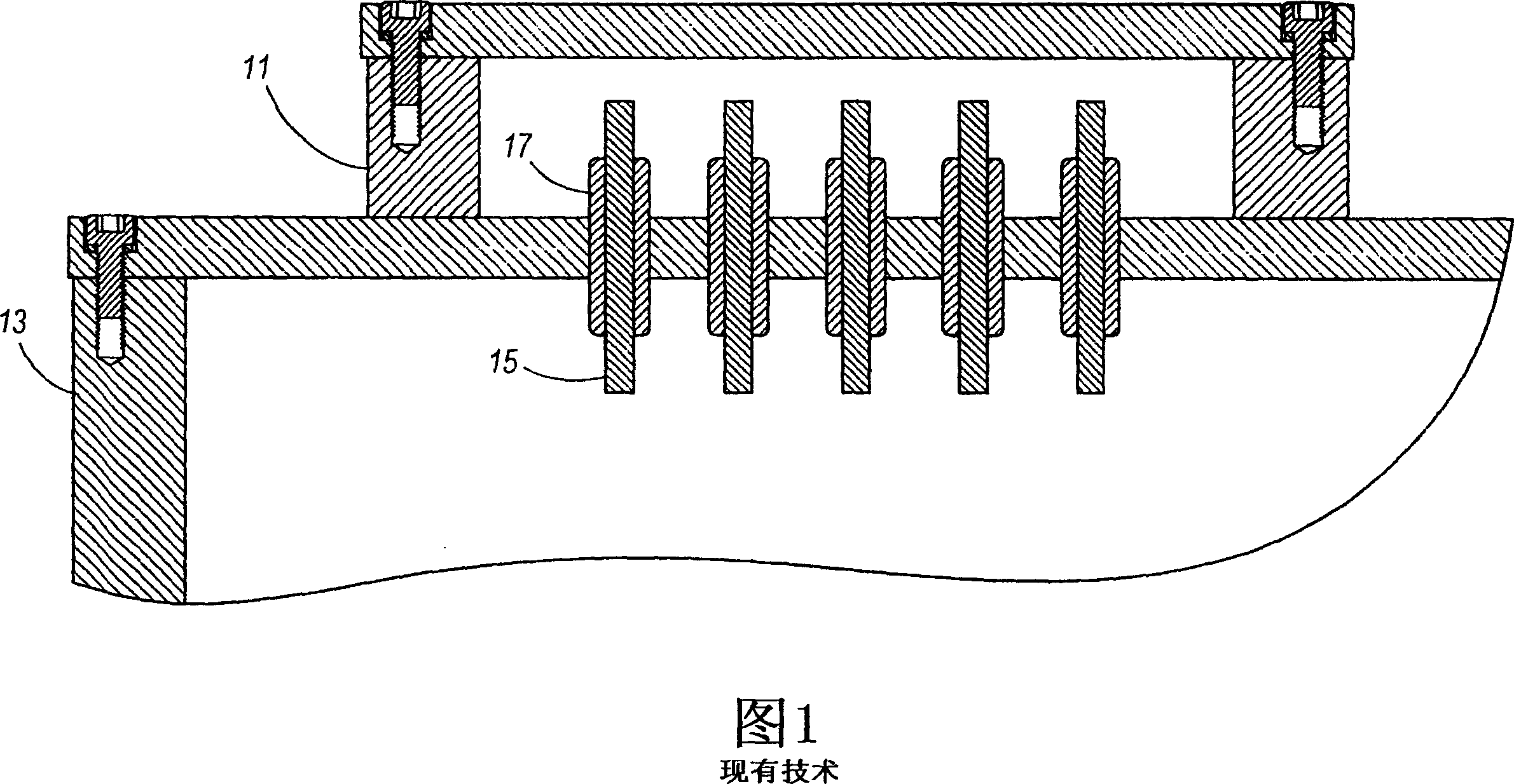
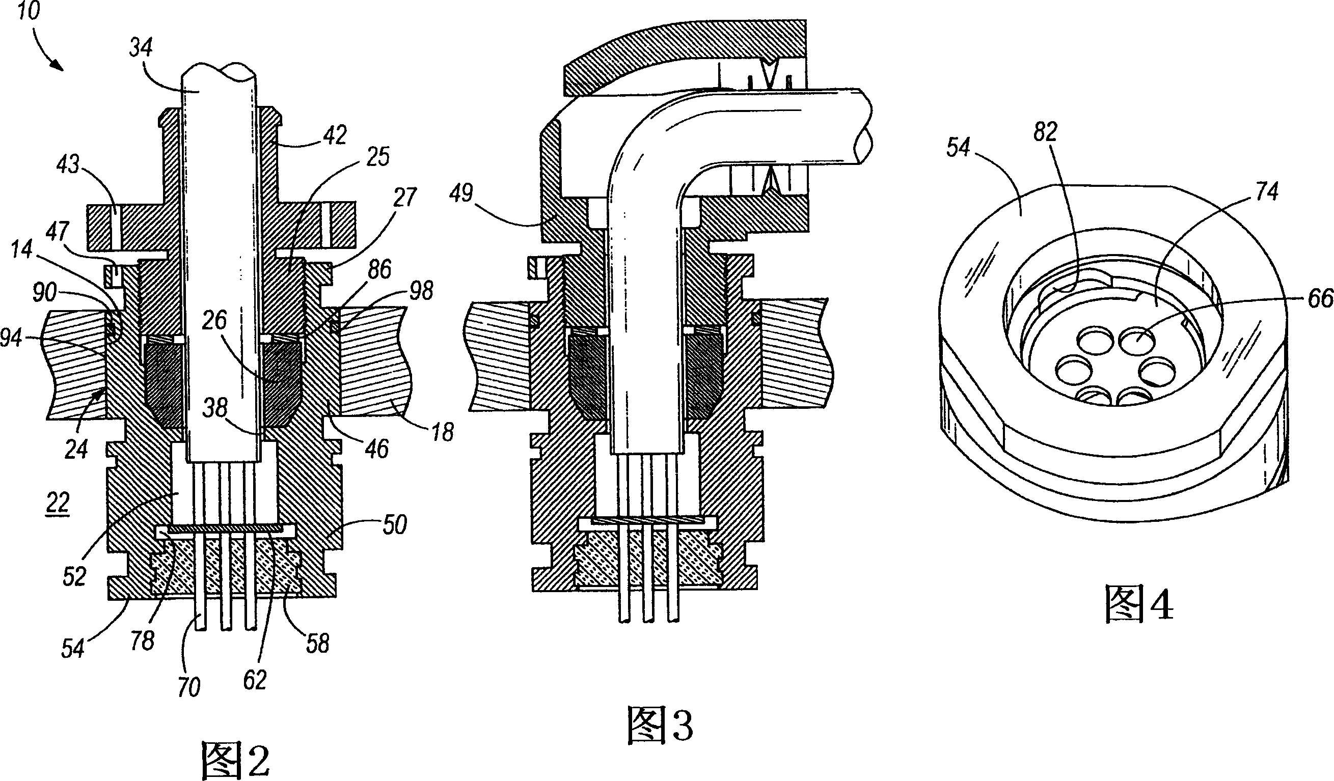
[0013] The present invention provides a small indirect entry cable gland assembly 10 that can be placed within a hole 14 in a wall 18 of a spark proof enclosure 22 to provide access for a single or multi-conductor cable 34 into the enclosure 22 . The jacket assembly 10 is designed to meet the above-mentioned indirect entry requirements of international standards for cables with a diameter of 5.4mm-66.8mm (IEC60079-0 and IEC60079-1 series).

[0014] More particularly, as shown, the cable gland assembly 10 includes a cable receiving jacket 42 having a gland nut 25 , a gland nut housing or stuffing box 24 , a grommet 26 , an insulator 58 and a cable 34 . The stuffing box 24 has a through opening 38 . The cable receiving jacket 42 is adapted to receive the cable 34 . The stuffing box 24 also has a grommet receiving portion 46 with the grommet 26 inside, adjacent to the cable receiving jacket 42 . More particularly, the compression nut 25 is threaded and is received in a threaded...


PUM


Abstract

A cable gland assembly adapted to receive a cable and to pass through an opening in a sparking enclosure wall, the cable gland assembly including a cable-receiving gland, a stuffing box, a grommet, an insulator and a cable. The stuffing box has an opening there through, and a grommet-receiving portion having the grommet therein. The grommet-receiving portion is adjacent the cable-receiving gland. The stuffing box also includes a gas terminal portion filled with gas and adjacent the grommet-receiving portion, and an insulator portion having the insulator therein and being adjacent the gas terminal portion.

Description

technical field [0001] The present invention relates to an assembly for allowing the penetration of cables into flameproof enclosures, and more particularly to the indirect entry of cables into sparking enclosures rated greater than 250 watts and 5 amps. Background technique [0002] As shown in Figure 1, the current indirect entry method involves installing the chamber 11 outside the flameproof enclosure 13, installing electrical terminals 15 inside the chamber 11, and providing insulation for each wire of each cable in the chamber Sleeve 17 , said cable then passes through the wall of housing 13 . This is an extremely costly way to achieve indirect introductions. Contents of the invention [0003] The present invention provides a simple cable gland assembly which meets the requirements of existing standards. This series of components is suitable for cables with a diameter of 5.4mm-66.8mm. Each cable is passed through a direct-entry jacket, after which the cable conduc...

Claims


Application Information

Patent Timeline
Patent Type & Authority Applications(China)
IPC IPC(8): H02G15/013
CPCH02G3/22H02G3/088Y10T16/05
Inventor 詹姆斯·科瑟曼乔纳森·达伊西尔万·兰德斯斯坦利·J·马松大卫·G·托马斯
Owner JOY MM DELAWARE INC
Why Eureka
Try Eureka