Zipper head structure

Inactive Publication Date: 2012-11-29
CHUNG CHWAN ENTERPRISE CO LTD
View PDF7 Cites 10 Cited by
  • Summary
  • Abstract
  • Description
  • Claims
  • Application Information

AI Technical Summary

Benefits of technology

[0007]The instant disclosure provides a zipper head structure, which can

Problems solved by technology

However, the aforementioned zipper head structure may be more difficult to assemble, involv

Method used


Image

  • Zipper head structure
  • Zipper head structure
  • Zipper head structure

Examples


Example

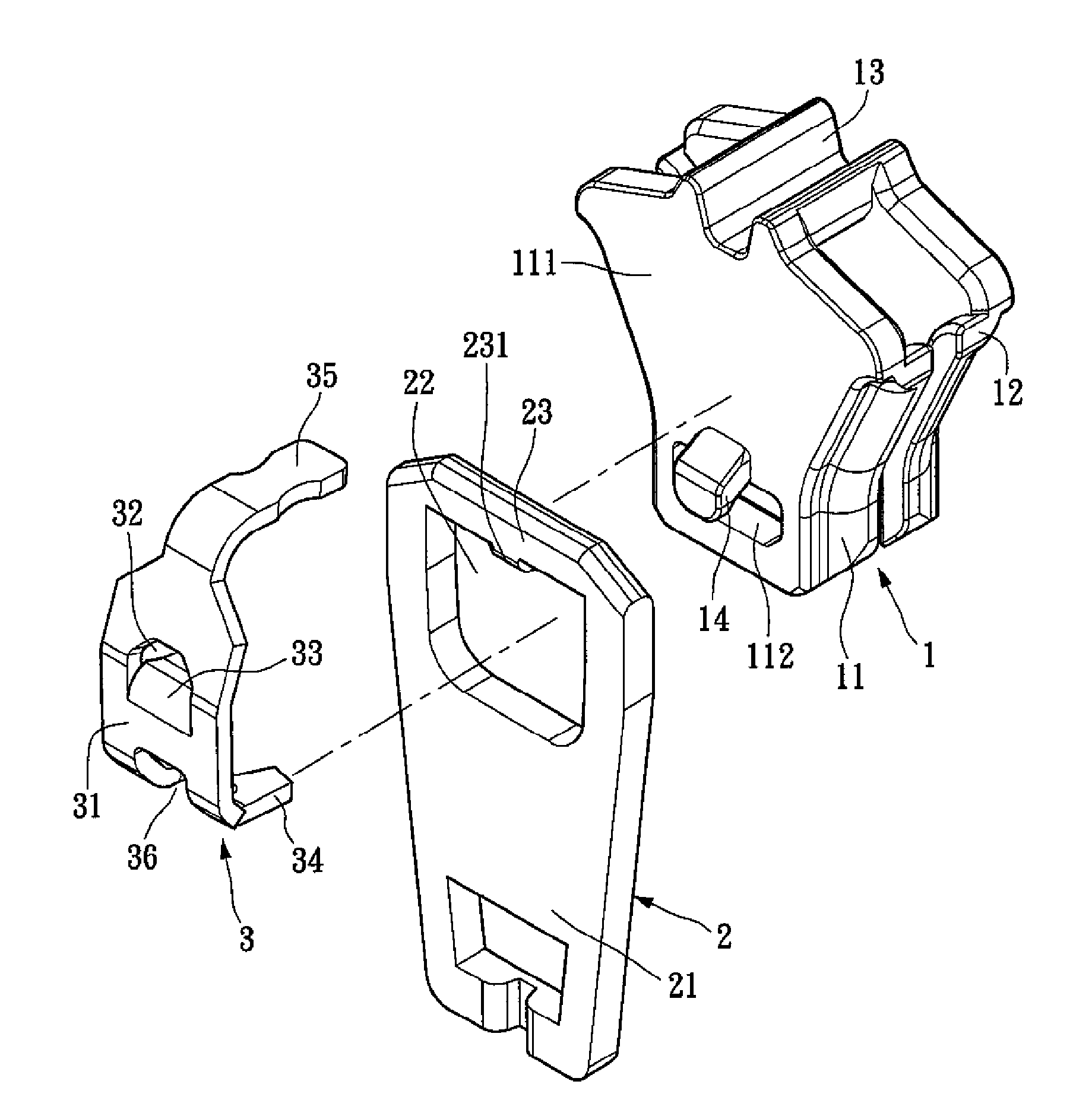
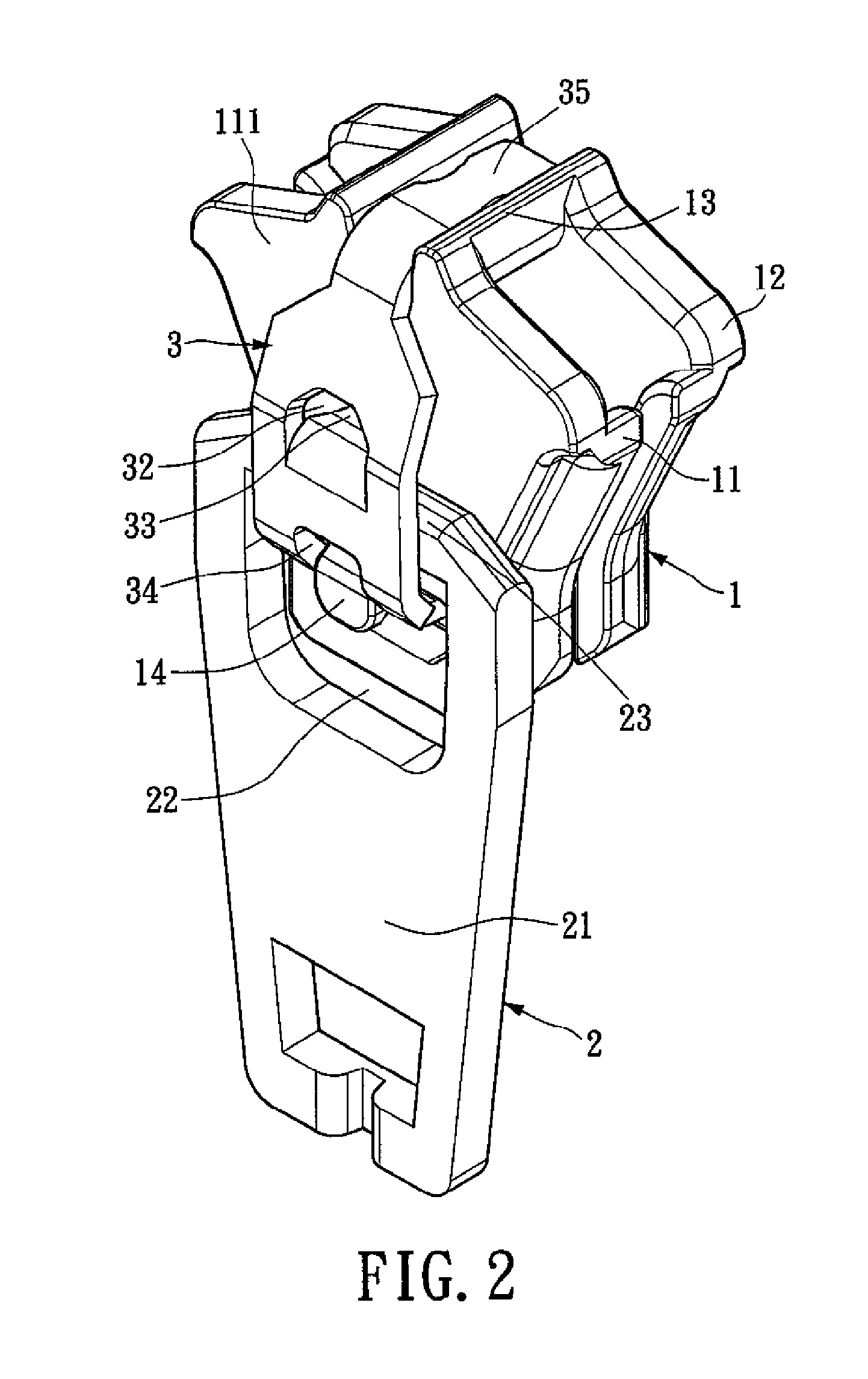
[0017]Please refer to FIGS. 2, 3, and 4, FIG. 2 shows an assembled view, and FIGS. 3, 4 show different views of an exploded view of a zipper head structure of the instant disclosure respectively. The zipper head structure comprises a slider body 1, a pull-tab 2, and a locking hook 3. The slider body 1 has a top wall 11, a bottom wall 12, a connecting portion 13, and a protrusion 14. Both ends of the connecting portion 13 are respectively connected with the top wall 11 and the bottom wall 12. The protrusion 14 is formed onto a top surface 111 of the top wall 11. The protrusion 14 is located on one end of the slider body 1. The connecting portion 13 is formed on another end of the slider body 1. The pull-tab 2 has a holding portion 21 on one end and an opening 22 formed on another end thereof. A hinge portion 23 is defined in between the opening 22 and the corresponding end of the pull-tab 2, with the hinge portion 23 being opposite of the holding portion 21. The pull-tab 2 is dispose...


PUM


Abstract

A zipper head structure is disclosed, which includes a slider body, a pull-tab, and a locking hook. The slider body has a protrusion which is formed on the slider body. The pull-tab has a holding portion and an opening. The protrusion is located in the opening of the pull-tab. The locking hook has a base portion which is located over the hinge portion. The locking hook is disposed on the slider body. The base portion has a through hole. A stopper is downwardly formed by one side of the through hole. The hinge portion is disposed between the protrusion and the stopper. Thereby, by utilizing the stopper of the locking hook which is integrally formed, the movement of the hinge portion is effectively confined for preventing the pull-tab from separating with the slider body when pulling the zipper.

Description

BACKGROUND OF THE INVENTION[0001]1. Field of the Invention[0002]The instant disclosure relates to a zipper head structure; more particularly, to a zipper head structure that prevents a pull tab of separating from the zipper.[0003]2. Description of Related Art[0004]In general, zippers are basic elements in clothing or accessories. Compare to buttons, the zippers are easier to use. A conventional zipper comprises a zipper head and a tape. The zipper head works with the tape to allow the pulling action. Recently, zippers has being used commonly for clothing, pants, backpack, and other accessories.[0005]Please refer to FIG. 1, which shows a sectional view for a standard zipper head structure. The zipper head structure comprises a slider body 1a, a pull-tab 2a, a locking hook 3a, and a stopper 4a. The pull-tab 2a is disposed onto the slider body 1a. A hinge portion 21a of the pull-tab 2a is located in back of a protrusion 11a of the slider body 1a, and which is located in front of a stop...

Claims


Application Information

Patent Timeline
IPC IPC(8): A44B19/26
CPCY10T24/2586A44B19/306
Inventor LIN, YU-PAU
Owner CHUNG CHWAN ENTERPRISE CO LTD
Why Eureka
Try Eureka