Charging assembly for electronic device

a charging assembly and electronic device technology, applied in the direction of digital data processing details, instruments, transportation and packaging, etc., can solve the problem that electronic devices can easily be stolen

Inactive Publication Date: 2012-11-29
HON HAI PRECISION IND CO LTD
View PDF5 Cites 33 Cited by
  • Summary
  • Abstract
  • Description
  • Claims
  • Application Information

AI Technical Summary

Problems solved by technology

However, in this method, the electronic device can easily be pulled out from the charging apparatus by any person without the need to enter a password or other identification (ID) authentication.
Therefore, the electronic device can easily be stolen because any person can easily remove the electronic device from the charging apparatus without any ill-effects.

Method used


Image

  • Charging assembly for electronic device
  • Charging assembly for electronic device
  • Charging assembly for electronic device

Examples


Embodiment Construction

[0016]The disclosure is illustrated by way of example and not by way of limitation in the figures of the accompanying drawings in which like references indicate similar elements. It should be noted that references to “an” or “one” embodiment in this disclosure are not necessarily to the same embodiment, and such references mean at least one.

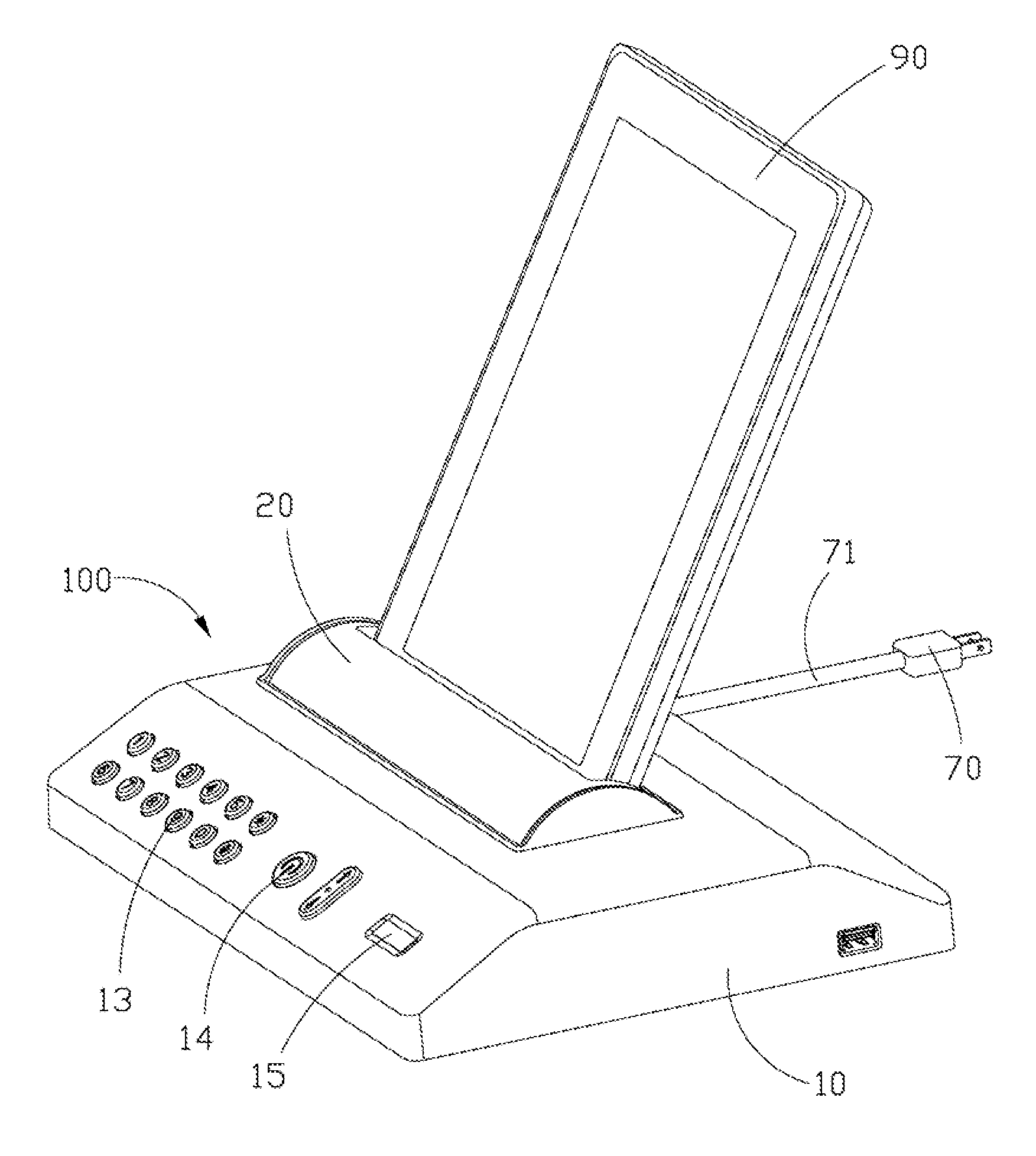
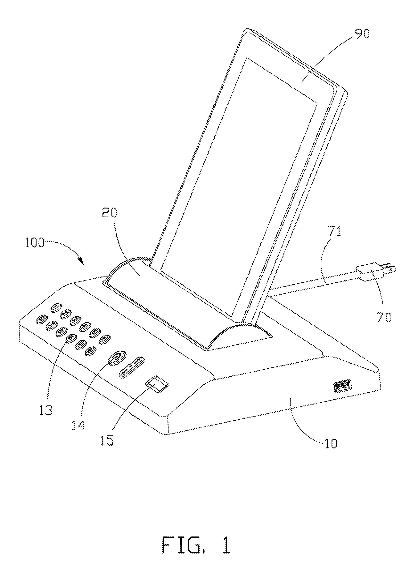
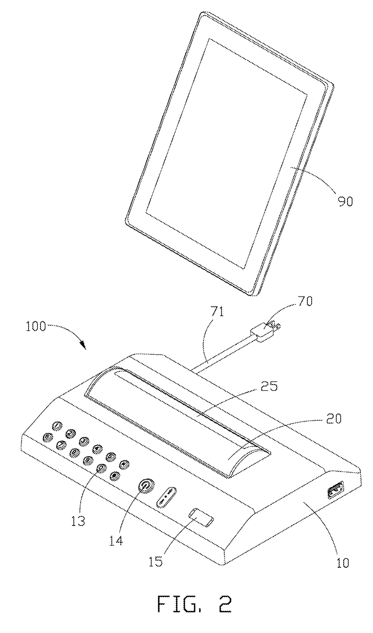
[0017]Referring to FIG. 1 and FIG. 2, a charging apparatus 100 is used to support and charge an electronic device 90, such as, tablet personal computer, cellular telephone and other portable electronic device, for example.

[0018]Also referring to FIG. 3, the charging apparatus 100 comprises a holding portion 10, a placement portion 20, a controlling portion 30, a circuit board portion 40 and a power input terminal 70. The placement portion 20 pivots on the holding portion 10 to receive and support the electronic device 90. The controlling portion 30 is secured on the placement portion 20 to engage with the electronic device 90. The circuit board p...


PUM


Abstract

A charging apparatus is used to support and charge an electronic device defining a latching slot and includes a holding portion, a placement portion and controlling portion. The placement portion engages with the holding portion and defines a latching notch aiming at the latching slot when the electronic device is received in the placement portion. The controlling portion is secured in the holding portion and includes a magnetic switch and a safety latch. The magnetic switch includes a movable shaft, and the safety latch includes a latching portion engaging with the movable shaft and pivoting to the placement portion, and a buckling portion engaging with the latching notch and the latching slot. The magnetic switch drives the movable shaft move to urge the latching portion rotating relative to the placement portion and to urge the buckling portion passing through the latching notch and engaging with the latching slot.

Description

BACKGROUND[0001]1. Technical Field[0002]The present disclosure relates to a charging assembly, and more particularly to a safety charging assembly.[0003]2. Description of Related Art[0004]In general, electronic devices, especially portable electronic devices, such as tablet personal computers, cellular telephones and other electronic devices, for example, are charged via electrically connecting charging apparatuses with power input terminals of the electronic devices. However, in this method, the electronic device can easily be pulled out from the charging apparatus by any person without the need to enter a password or other identification (ID) authentication. Therefore, the electronic device can easily be stolen because any person can easily remove the electronic device from the charging apparatus without any ill-effects.[0005]Therefore, a need exists in the industry to overcome the described limitations.BRIEF DESCRIPTION OF THE DRAWINGS[0006]Many aspects of the present embodiments...

Claims


Application Information

Patent Timeline
Patent Type & Authority Applications(United States)
IPC IPC(8): H02J7/00
CPCG06F1/1632H02J7/0044G06F1/263
Inventor LEE, CHIEN-HUNGWONG, SHIH-CHI
Owner HON HAI PRECISION IND CO LTD
Why Eureka
Try Eureka