Static plasma grid evacuation techniques for vacuum insulating glass (VIG) units

a plasma grid and vacuum insulating glass technology, applied in glass reforming apparatus, glass making apparatus, glass making tools, etc., can solve the problems of b>6 time-consuming and laborious, and achieve the effect of quick and/or efficient cavity evacuation

Inactive Publication Date: 2012-12-06
GUARDIAN GLASS LLC
View PDF2 Cites 55 Cited by
  • Summary
  • Abstract
  • Description
  • Claims
  • Application Information

AI Technical Summary

Benefits of technology

[0009]Another aspect of certain example embodiments relates to injecting a gas (e.g., argon, nitrogen, oxygen, hydrogen, etc.) into the internal cavity of a thermally insulating panel, and thereafter inductively ignite a plasma within the cavity by at least partially ionizing the gas. It has been fou

Problems solved by technology

Unfortunately, it typically takes twelve minutes or more in order to evacuate cavity 6 to such a low pressure.
This lengthy period of t

Method used


Image

  • Static plasma grid evacuation techniques for vacuum insulating glass (VIG) units
  • Static plasma grid evacuation techniques for vacuum insulating glass (VIG) units
  • Static plasma grid evacuation techniques for vacuum insulating glass (VIG) units

Examples


examples

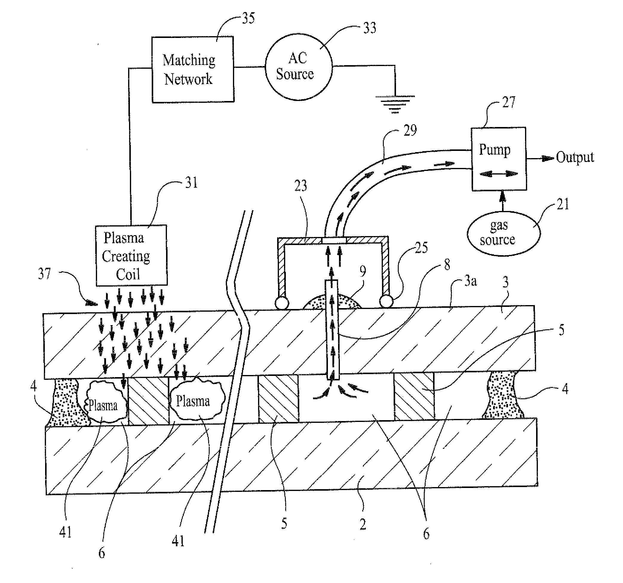
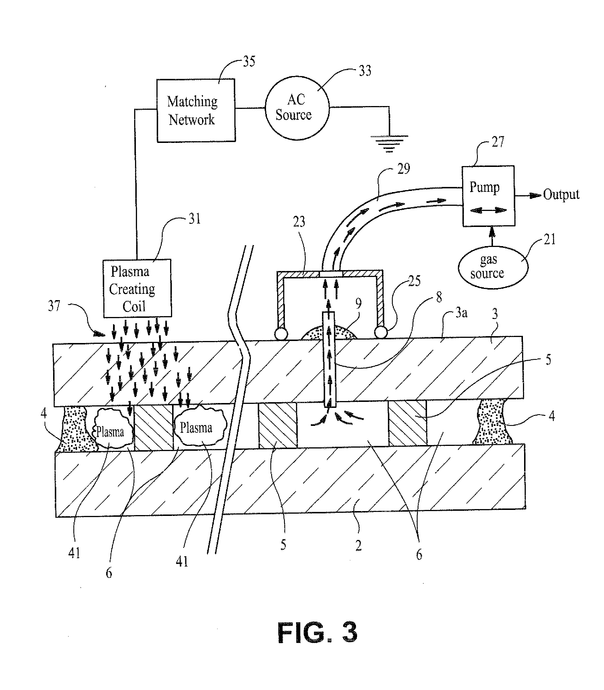
[0048]Six (6) different examples were carried out in order to illustrate the advantage(s) of igniting plasma 41 within cavity 6. Three comparative examples (comparative Examples 1-3) were performed without igniting a plasma in cavity 6, and three corresponding examples utilizing the same gases were carried out with ignition of plasma 41 in cavity 6 (Examples 4-6). It will be shown below that the examples in which plasma 41 was ignited in the space / cavity 6 (i.e., Examples 4-6) had evacuation times much less than the comparative examples where no plasma was ignited. In all six examples, tube 8 was 6 mm in length, with an inner diameter of 1.65 mm.

[0049]FIG. 5 illustrates certain steps carried out in the three examples in which plasma was ignited (i.e., Examples 4-6), while FIGS. 6-8 are also illustrative of the examples.

[0050]Examples 1-3 were performed for comparative purposes only. In Example 1, cavity 6 was twice purged with argon (Ar) gas and thereafter evacuated to the pressures...


PUM

PropertyMeasurementUnit
Angleaaaaaaaaaa
Timeaaaaaaaaaa
Pressureaaaaaaaaaa

Abstract

A thermally insulating panel (e.g., vacuum IG window unit) includes first and second opposing substrates spaced apart from one another by a plurality of spacers. A low pressure space is defined between the substrates, and is hermetically sealed off by at least one edge seal. During evacuation of the space, a plasma is ignited within the space via a static grid assembly in order to reduce the time needed to evacuate the space down and/or to help remove debris from within the space to the desired low pressure.

Description

[0001]Certain example embodiments of this invention relate to vacuum insulating glass (VIG) units, and / or methods of making the same. More particularly, certain example embodiments of this invention relate to plasma-enhanced evacuation techniques for the internal cavity of a VIG unit or thermally insulating panel, wherein the plasma-enhanced evacuation techniques are performed in connection with a static plasma grid or array.BACKGROUND AND SUMMARY OF EXAMPLE EMBODIMENTS OF THE INVENTION[0002]Vacuum IG units are known in the art. For example, see U.S. Pat. Nos. 5,664,395; 5,657,607; 5,897,927; 5,902,652; and 6,261,652, the disclosures of which are all hereby incorporated herein by reference. See also U.S. Pat. No. 6,692,600, the entire contents of which is hereby incorporated herein by reference.[0003]FIGS. 1-2 illustrate a conventional vacuum IC unit. IG unit 1 includes a pair of spaced apart glass substrates 2 and 3 that enclose an evacuated or low pressure space / cavity 6 therebetw...

Claims


Application Information

Patent Timeline
IPC IPC(8): C03C27/00
CPCY02B80/24E06B3/6775Y02A30/249Y02B80/22C03C27/06
Inventor MILLER, ROBERT A.DEAR, RYAN L.JONES, JEFFREY A.
Owner GUARDIAN GLASS LLC
Why Eureka
Try Eureka