Particle beam treatment device and irradiation dose setting method of the particle beam treatment device

a treatment device and particle beam technology, applied in the field of particle beam treatment devices, can solve the problem of not being able to measure directly the dose of biology in the target volume tv during irradiation

Active Publication Date: 2012-12-13
MITSUBISHI ELECTRIC CORP
View PDF3 Cites 19 Cited by
  • Summary
  • Abstract
  • Description
  • Claims
  • Application Information

AI Technical Summary

Benefits of technology

[0021]In a particle beam treatment device in accordance with a scanning irradiation method, by using an absorbed dose which has less change i

Problems solved by technology

On the other hand, there is not any method to measure directly the biology dose in the target volume TV during irradiation.
According to the technology described in Patent Document 1 or Pa

Method used


Image

  • Particle beam treatment device and irradiation dose setting method of the particle beam treatment device
  • Particle beam treatment device and irradiation dose setting method of the particle beam treatment device
  • Particle beam treatment device and irradiation dose setting method of the particle beam treatment device

Examples


embodiment 1

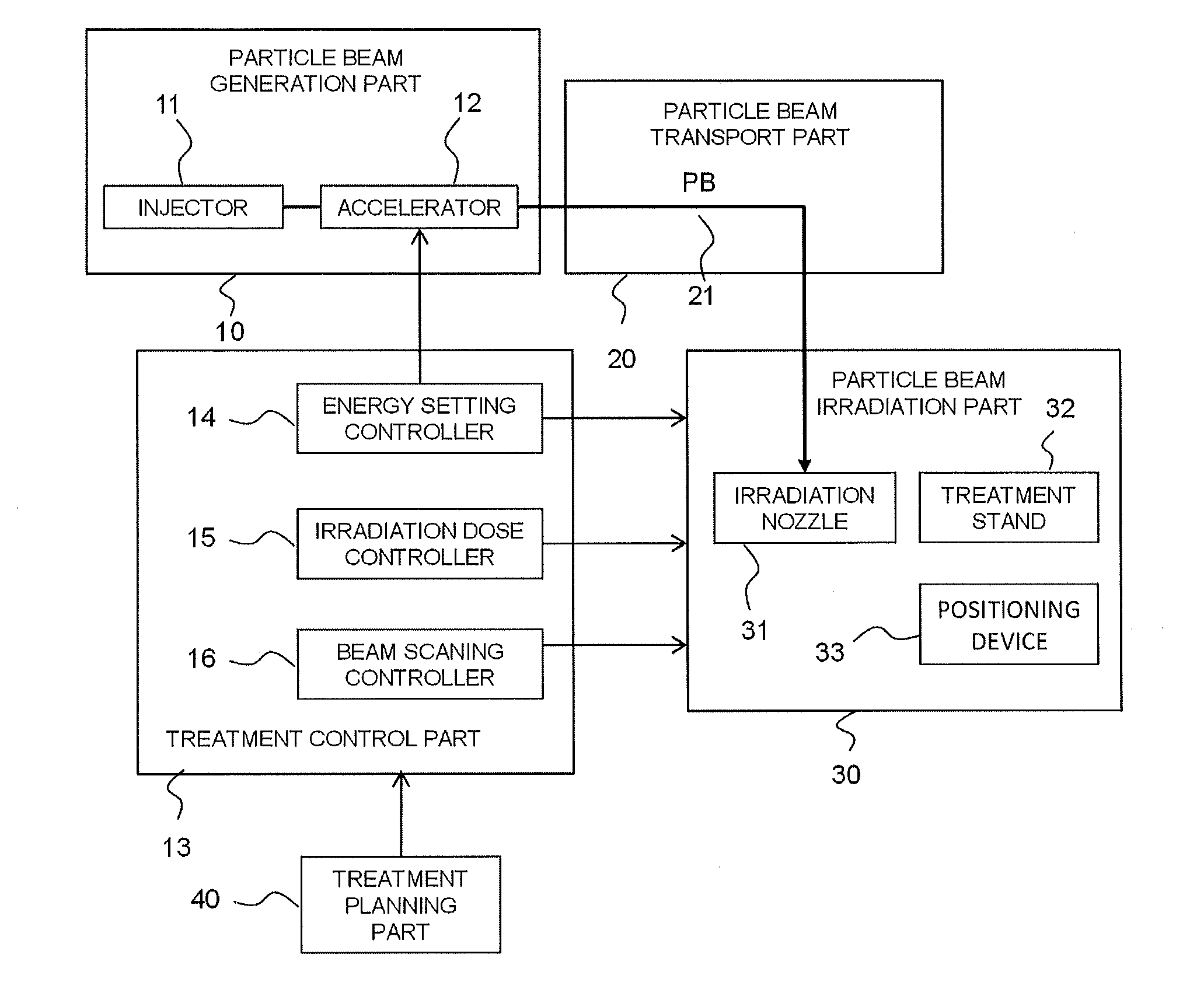
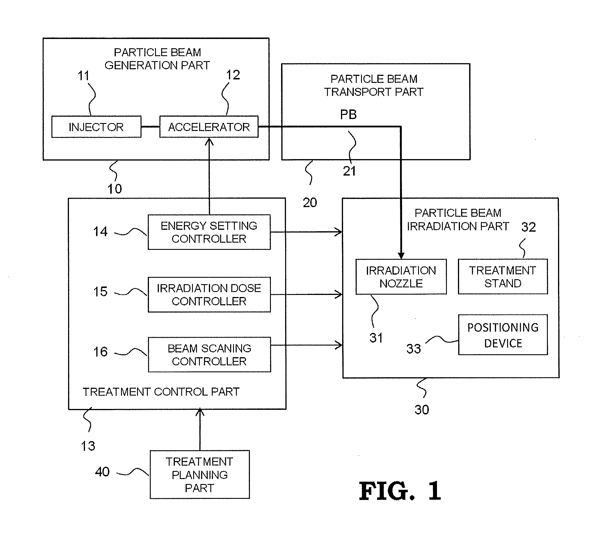
[0040]FIG. 1 is a block diagram schematically illustrating the configuration of a particle beam treatment device according to the present invention and FIG. 2 is a bird's-eye view schematically illustrating an example of whole configuration of a particle beam treatment device. As shown in FIGS. 1 and 2, the particle beam treatment device includes a particle beam generation part 10, a particle beam transport part 20, and two particle beam irradiation parts 30. FIG. 2 shows a particle beam treatment device having two particle beam irradiation parts, however, number of particle beam irradiation part is not limited to two, a particle beam treatment device having one particle beam irradiation part or three or more particle beam irradiation parts may be acceptable. For simplification, FIG. 1 shows a particle beam treatment device having one particle beam irradiation part. For reasons of application of radiation safety management and the like, the particle beam generation part 10 and the p...

embodiment 2

[0050]FIGS. 6 to 10 are diagrams for describing the details of operation of a particle beam treatment device according to EMBODIMENT 2 of the present invention, that is, acquisition and storing of radiation source basic data in the step ST1 shown in FIG. 5. FIG. 6 is an outline configuration diagram showing a device used in a first step in EMBODIMENT 2. In FIG. 6, the same symbol shows a part which is same as that in FIG. 1 or a corresponding part. A water phantom 60 is irradiated with a pencil beam P having a predetermined beam diameter which is emitted from an irradiation nozzle 31, without scanning the pencil beam P in the X or the Y direction. A dose sensor 341 comprising an ion chamber is arranged between the irradiation nozzle 31 and the water phantom 60. A parallel board-type chamber 61 is provided, to be movable at a part of the water phantom 60 which is irradiated with the pencil beam P, in the advancing direction of the pencil beam P, that is, the Z direction. The charge a...

embodiment 3

[0057]FIGS. 11 to 13 are diagrams for describing the details of operation of a particle beam treatment device in EMBODIMENT 3 of the present invention, that is, acquisition and storing of basic data of the spot scanning irradiation which is the operation in the step ST2 shown in FIG. 5. FIG. 11 is an outline configuration diagram showing a main part of a particle beam treatment device used in EMBODIMENT 3. In the step ST2, a pencil beam P is scanned, and the absorbed dose data is acquired by a thimble chamber 62 which is set at a predetermined position at the reference depth D0. FIG. 12 shows the image of the spot scanning irradiation which is performed on a surface of the reference depth in this measurement. When this measurement is performed, the condition to make the dose distribution at a part in the reference depth (plato), which is applied by the irradiation for one slice, that is, by irradiation with a certain energy, uniform is obtained. On this occasion, this measurement is...


PUM


Abstract

A particle beam treatment device includes an irradiation nozzle which moves a particle beam in a direction which is perpendicular to an advancing direction; a dose monitor which measures the dose of the particle beam; a planning part which sets the irradiation dose applied to a target volume; and a controlling part which controls the irradiation dose applied to a target volume based on irradiation dose set value which is set by a value measured by the dose monitor and the planning part, wherein the planning part stores the absorbed dose distribution data in the depth direction which is prepared in advance using the absorbed dose at the reference depth which is a predetermined position nearer to an incident side of the particle beam than the position of Bragg peak as the reference and calculates the irradiation dose set value using the absorbed dose at the reference depth.

Description

TECHNICAL FIELD[0001]This invention relates to a particle beam treatment device which performs the treatment of cancer by radiating a particle beam, especially to an irradiation dose setting method.BACKGROUND ART[0002]The treatment of a cancer is one of applications of radiation beam. Recently, particle beam treatment in which a particle beam such as a proton beam or a carbon beam is radiated on the cancer cell has been attracted attention. First of all, the characteristic of a particle beam radiation in which the particle beam is radiated to kill a cancer cell will be described. In a case where various kinds of radiation beams are radiated on a human body, the dose distribution of the radiation beam in the human body changes as shown in FIG. 18. As shown in FIG. 18, among various kinds of radiations, a photon beam such as an X-ray or a gamma ray has a relative dose which becomes maximum in a portion close to the surface of the body, and is decreased as the depth from the surface of...

Claims


Application Information

Patent Timeline
IPC IPC(8): A61N5/10
CPCA61N5/1043A61N2005/1087A61N5/1036
Inventor IKEDA, MASAHIROHARADA, HISASHITAKAHASHI, OSAMU
Owner MITSUBISHI ELECTRIC CORP
Why Eureka
Try Eureka