Steering apparatus

a technology of steering apparatus and cylinder, which is applied in the direction of steering column, steering parts, vehicle components, etc., can solve the problems of limited layout of components and limited number of components that may be arranged, and achieve the effect of wide arrangement space and preventing excessive downward displacemen

Inactive Publication Date: 2012-12-20
JTEKT CORP +1
View PDF14 Cites 31 Cited by
  • Summary
  • Abstract
  • Description
  • Claims
  • Application Information

AI Technical Summary

Benefits of technology

[0009]The invention provides a steering apparatus that is able to prevent excessive downward displacement of a steering apparatus that is detached from a vehicle body in the event of a secondary collision, and that is able to ensure a relatively wide arrangement space on the driver seat side with respect to the steering apparatus.

Problems solved by technology

This causes some problems that, for example, the types or the number of the components that may be arranged are limited and the layout of component arrangement is limited.

Method used


Image

  • Steering apparatus
  • Steering apparatus
  • Steering apparatus

Examples


first embodiment

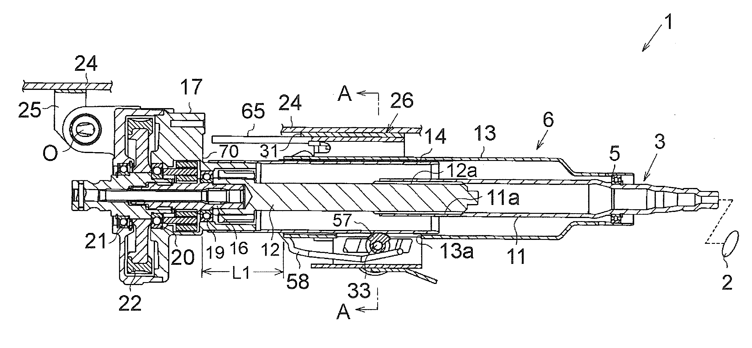
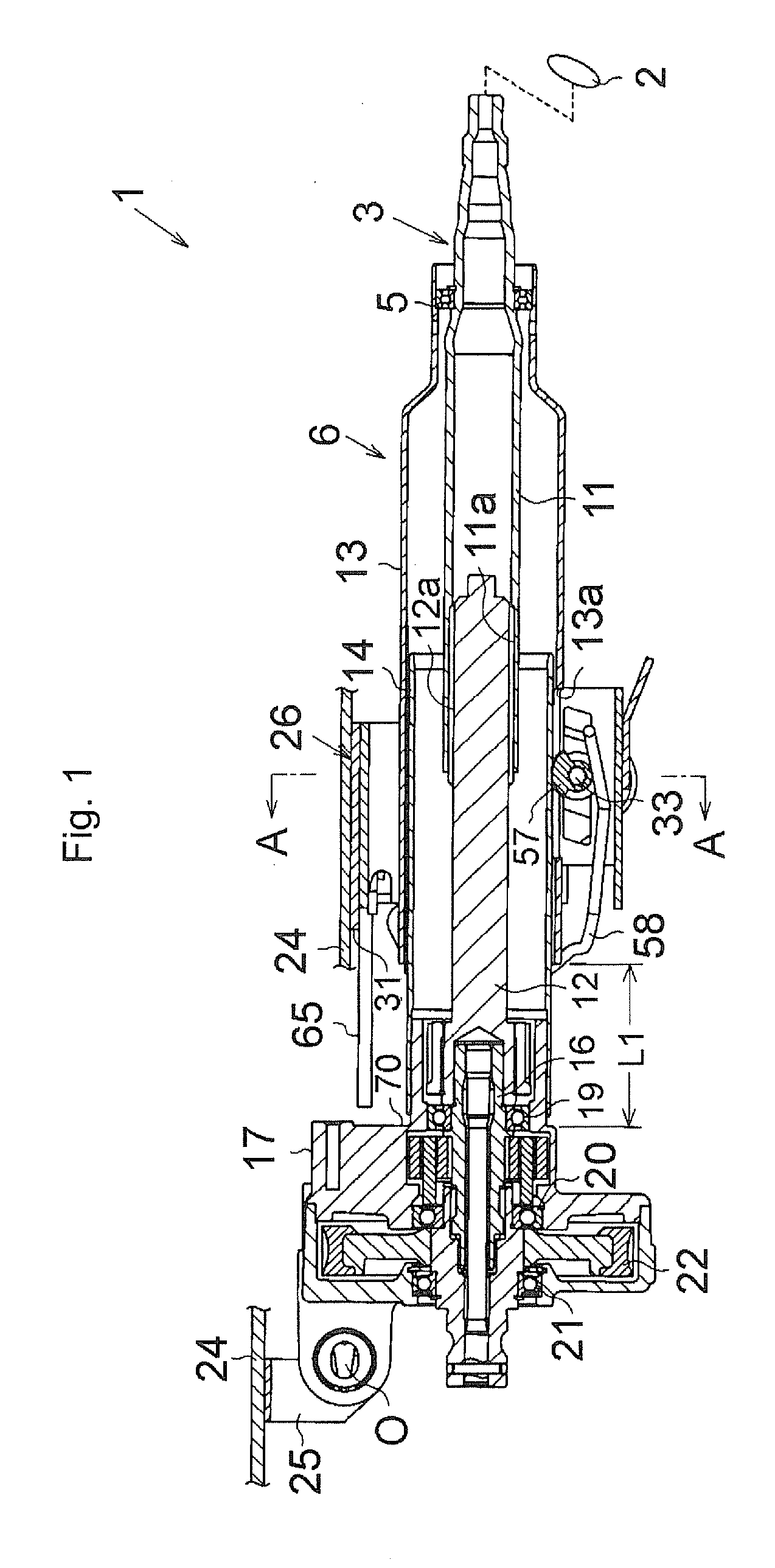
[0022]First, the invention will be described with reference to FIG. 1 to FIG. 6. As shown in FIG. 1, a steering apparatus 1 includes a steering shaft 3. A steering wheel 2 is fixed to a rear-side (right-side in FIG. 1) end portion of the steering shaft 3 (the rear-side end portion is the end portion closer to the rear of the vehicle than the other end portion). The steering shaft 3 is supported by a bearing 5, so that the steering shaft 3 is rotatably accommodated in a steering column 6. A front-side (left-side in FIG. 1) end portion of the steering shaft 3 is coupled to an intermediate shaft (not shown) via a universal joint (the front-side end portion is the end portion closer to the front of the vehicle than the rear-side end portion). Thus, rotation and steering torque resulting from a steering operation are transmitted to a steered mechanism, such as a rack and pinion mechanism. The steered mechanism changes the steered angle of steered wheels (not shown). Note that the steerin...

second embodiment

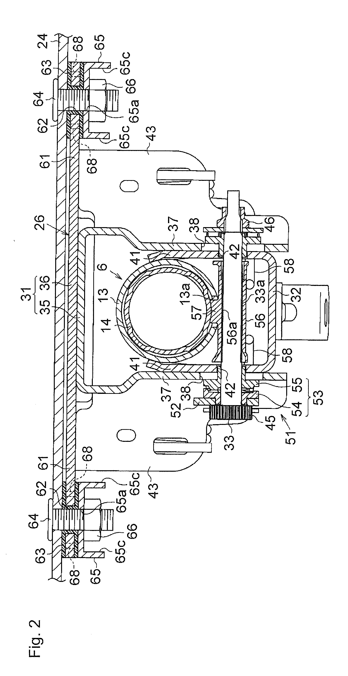
[0061]The restricting portion of each guide member is not limited to the restricting wall 65b that is brought into contact with the rear end face of the capsule 63. For example, as shown in FIG. 7, an elliptical annular protrusion 65d is formed around the bolt insertion hole 65a of each guide member 65, and an annular recess 63e that is engageable with the annular protrusion 65d is formed on the lower face of the capsule 63 (second embodiment). Then, at the time of fitting each guide member 65, the annular protrusion 65d is fitted into the annular recess 63e to thereby restrict the rotation of the guide member 65 that extends toward the front of the vehicle. With this configuration as well, it is possible to avoid an inconvenience that, at the time of finishing fastening the nut 66 to the shank of the corresponding bolt 64, the guide member 65 rotates together with the nut 66 due to friction between the nut 66 and the guide member 65 and the direction in which the guide member 65 ex...


PUM


Abstract

A steering column includes an impact absorbing mechanism that absorbs an impact through contraction, that is, movement of an outer tube relative to an inner tube in the event of a secondary collision. Capsules are fixed to extended portions of a vehicle body-side bracket so as to be detachable when a load higher than or equal to a predetermined load, directed toward a front of a vehicle, is applied to the body-side bracket. Guide members oriented to extend toward the front of the vehicle are fixedly fastened, using bolts and nuts, to a mounting stay that constitutes a vehicle body with the capsules held therebetween. The steering column detached from the vehicle body-side bracket in the event of the secondary collision makes collapsing movement while the paired extended portions extending at both ends in a vehicle-width direction of the vehicle body-side bracket slide over upper faces of the guide members.

Description

INCORPORATION BY REFERENCE / RELATED APPLICATION[0001]This application claims priority to Japanese Patent Application No. 2011-134331 filed on Jun. 16, 2011 the disclosure of which, including the specification, drawings and abstract, is incorporated herein by reference in its entirety.BACKGROUND OF THE INVENTION[0002]1. Field of the Invention[0003]The invention relates to a steering apparatus that is configured such that a steering column is detached from a vehicle body when a load higher than or equal to a predetermined load, which is directed toward the front of a vehicle, is applied to the steering apparatus in the event of, for example, a secondary collision.[0004]2. Discussion of Background[0005]For example, Japanese Patent Application Publication No. 2011-025856 (JP 2011-025856A) describes a steering apparatus that is configured such that when a vehicle frontal collision occurs and a driver collides with a steering wheel due to an inertial action (secondary collision occurs), a ...

Claims


Application Information

Patent Timeline
Patent Type & Authority Applications(United States)
IPC IPC(8): B62D1/19
CPCB62D1/195
Inventor KUROUMARU, YOSHIKAZU
Owner JTEKT CORP
Why Eureka
Try Eureka