Pressure balanced valve

Active Publication Date: 2012-12-20
BROOKS INSTRUMENT
View PDF9 Cites 27 Cited by
  • Summary
  • Abstract
  • Description
  • Claims
  • Application Information

AI Technical Summary

Benefits of technology

[0009]The disclosed embodiments also include a mass flow controller. The mass flow controller includes a flow path connected to a first port of the pressure balancing valve assembly as described above. The mass flow controller also includes a flow sensor assembly for

Problems solved by technology

While solenoid valves work great for low flows, they typically have problems when applied to control flows greater than about 100 Standard Liters per Minute (slpm).

Method used


Image

  • Pressure balanced valve
  • Pressure balanced valve
  • Pressure balanced valve

Examples


Embodiment Construction

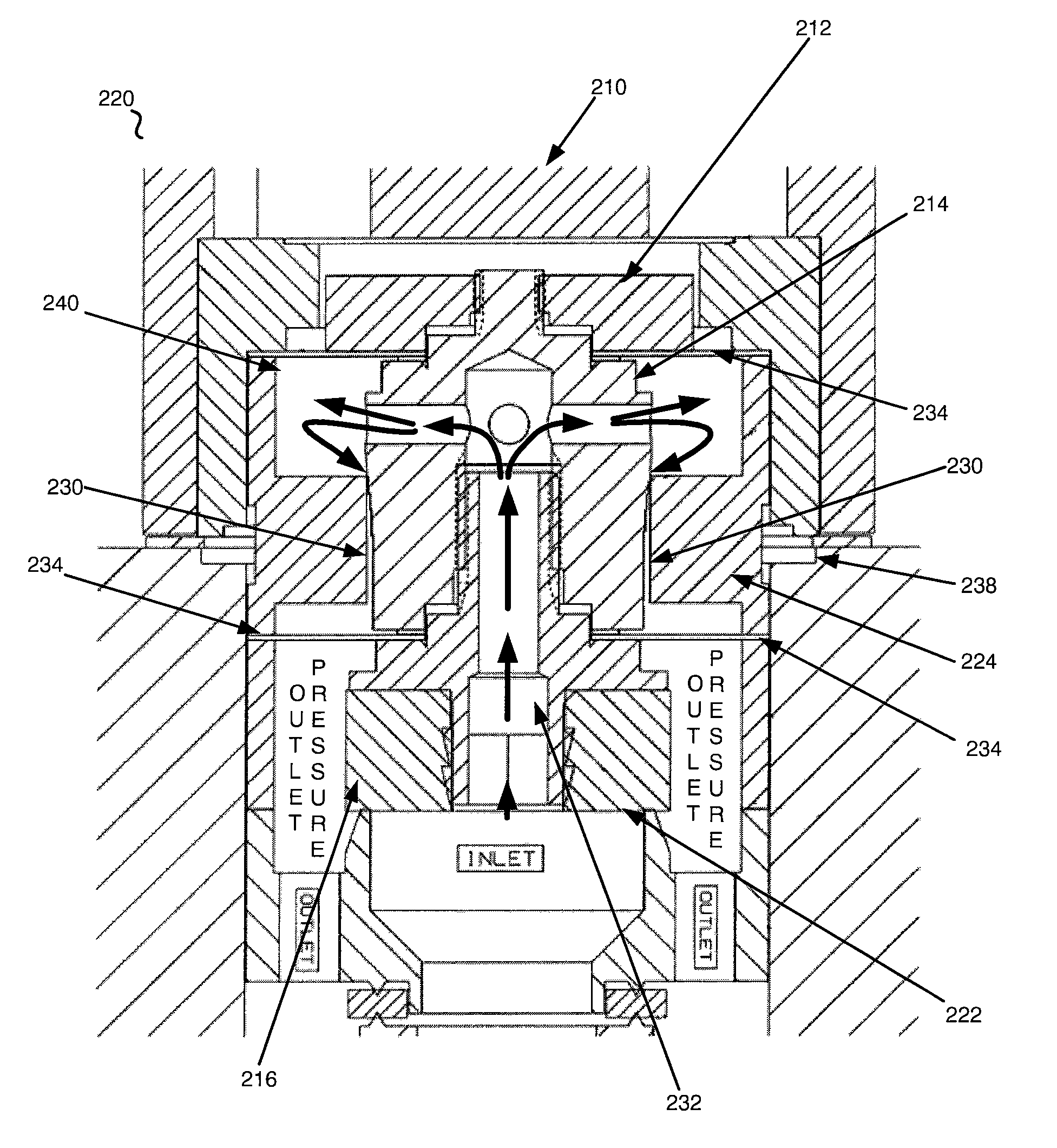
[0015]The disclosed embodiments include an apparatus and method for creating a pressure balance valve that eliminates the problems associated with existing designs. The disclosed embodiments may be utilized with a mass flow controller, such as, but not limited to, the mass flow controllers disclosed in U.S. Patent Publication 20110191038 and U.S. Pat. No. 6,343,617, the teachings of which are hereby fully incorporated herein.

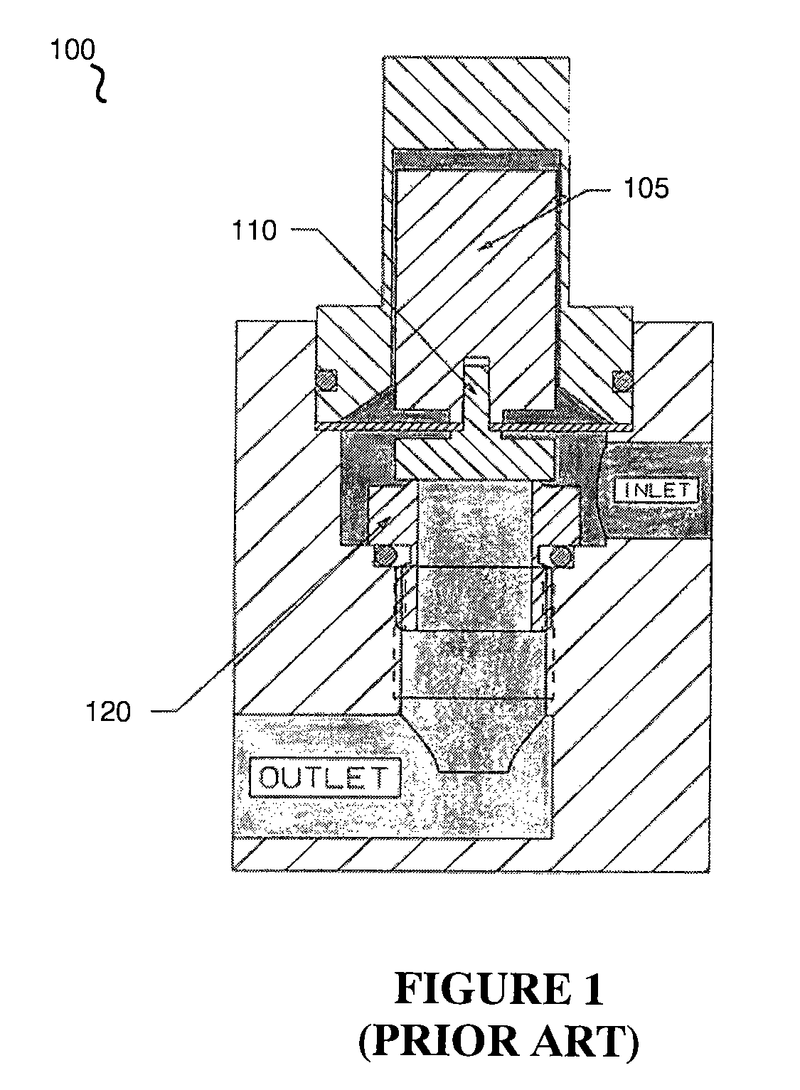
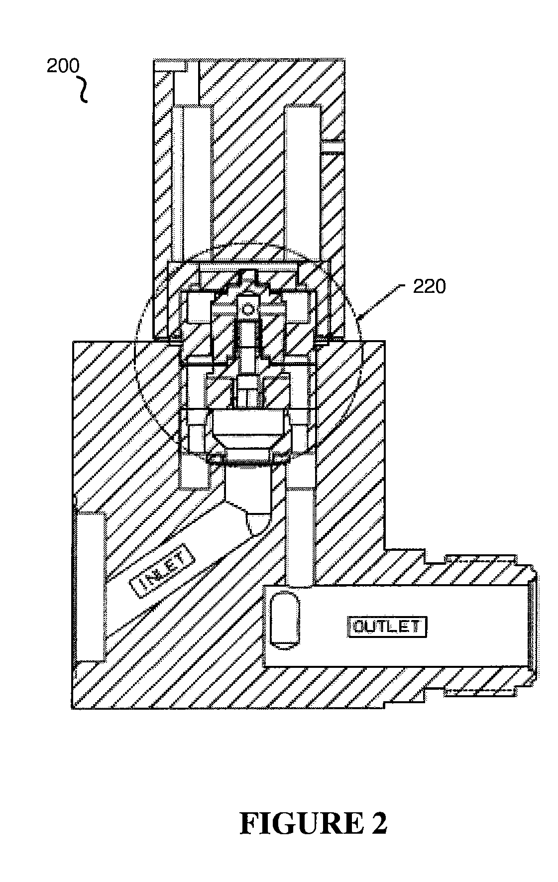
[0016]The disclosed embodiments and advantages thereof are best understood by referring to FIGS. 1-4 of the drawings, like numerals being used for like and corresponding parts of the various drawings. Other features and advantages of the disclosed embodiments will be or will become apparent to one of ordinary skill in the art upon examination of the following figures and detailed description. It is intended that all such additional features and advantages be included within the scope of the disclosed embodiments. Further, the illustrated figures are only exempla...


PUM


Abstract

The disclosed embodiments include a pressure balance valve that solves one or more problems associated with existing designs. For example, in one embodiment, a pressure balancing valve assembly is disclosed that provides a low cost frictionless assembly that is constructed to not seal the leak path between an inlet port and an outlet port. Instead, this leak path is minimized with small angle tapered plunger and a precision bored annulus to provide a defined area for the pressure drop to occur and to limit the flow from the inlet to the outlet.

Description

CROSS-REFERENCE TO RELATED APPLICATIONS[0001]This application claims priority to U.S. Provisional Patent Application Ser. No. 61 / 496,916 filed on Jun. 14, 2011, the entire teachings of which are incorporated herein.BACKGROUND OF THE INVENTION[0002]1. Field of the Invention[0003]The present invention relates generally to methods and systems for controlling fluid flow, and more particularly to a pressure balanced valve.[0004]2. Discussion of the Related Art[0005]Many industrial processes require precise control of various process fluids. For example, in the semiconductor industries, mass flow controllers are used to precisely measure and control the amount of a process fluid that is introduced to a process chamber. The term fluid is used herein to describe any type of matter in any state that is capable of flow. It is to be understood that the term fluid applies to liquids, gases, and slurries comprising any combination of matter or substance to which controlled flow may be of interes...

Claims


Application Information

Patent Timeline
IPC IPC(8): G05D7/06F16K31/06
CPCF16K31/0655F16K39/022G05D7/0635F16K31/0693F16K1/00F16K47/08
Inventor ROBERTSON, III, WALTER DENNIS
Owner BROOKS INSTRUMENT
Why Eureka
Try Eureka