Projected user interface onto the surface of an appliance

a projectable, user-friendly technology, applied in the field of projectable displays, can solve the problems of increasing the cost of manufacturing an appliance, limited space on the backsplash of an appliance, and increasing the cost of touch screen interfaces

a projectable, user-friendly technology, applied in the field of projectable displays, can solve the problems of increasing the cost of manufacturing an appliance, limited space on the backsplash of an appliance, and increasing the cost of touch screen interfaces

US20120327201A1Active Publication Date: 2012-12-27HAIER US APPLIANCE SOLUTIONS INC

Image

  • Projected user interface onto the surface of an appliance
  • Projected user interface onto the surface of an appliance
  • Projected user interface onto the surface of an appliance

Examples


Embodiment Construction

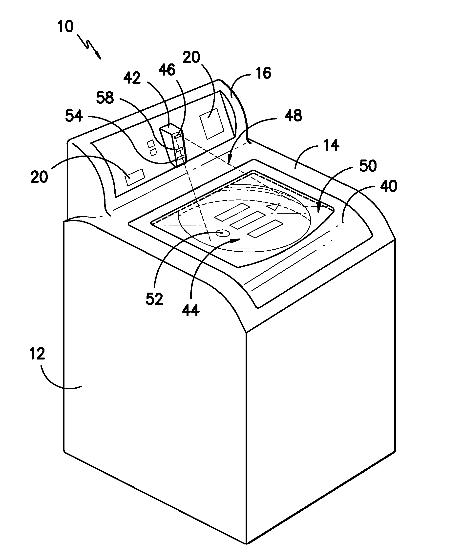
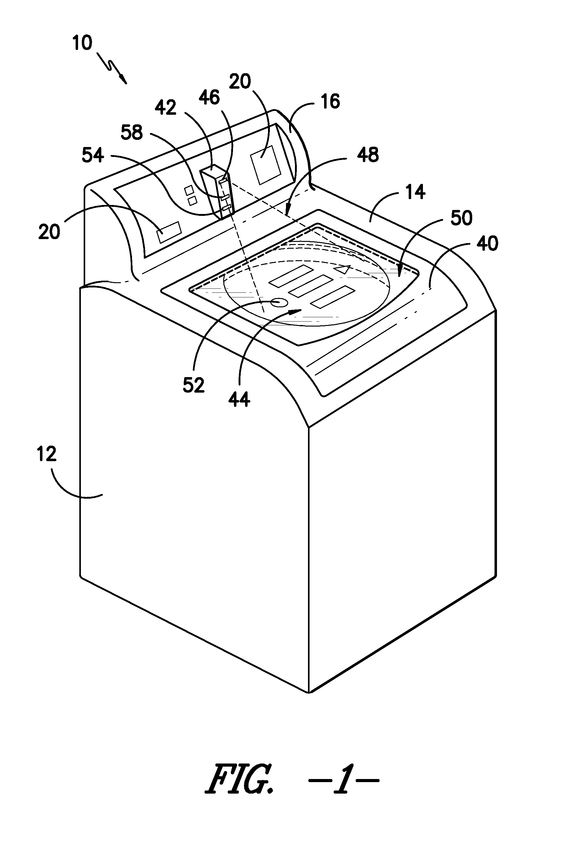
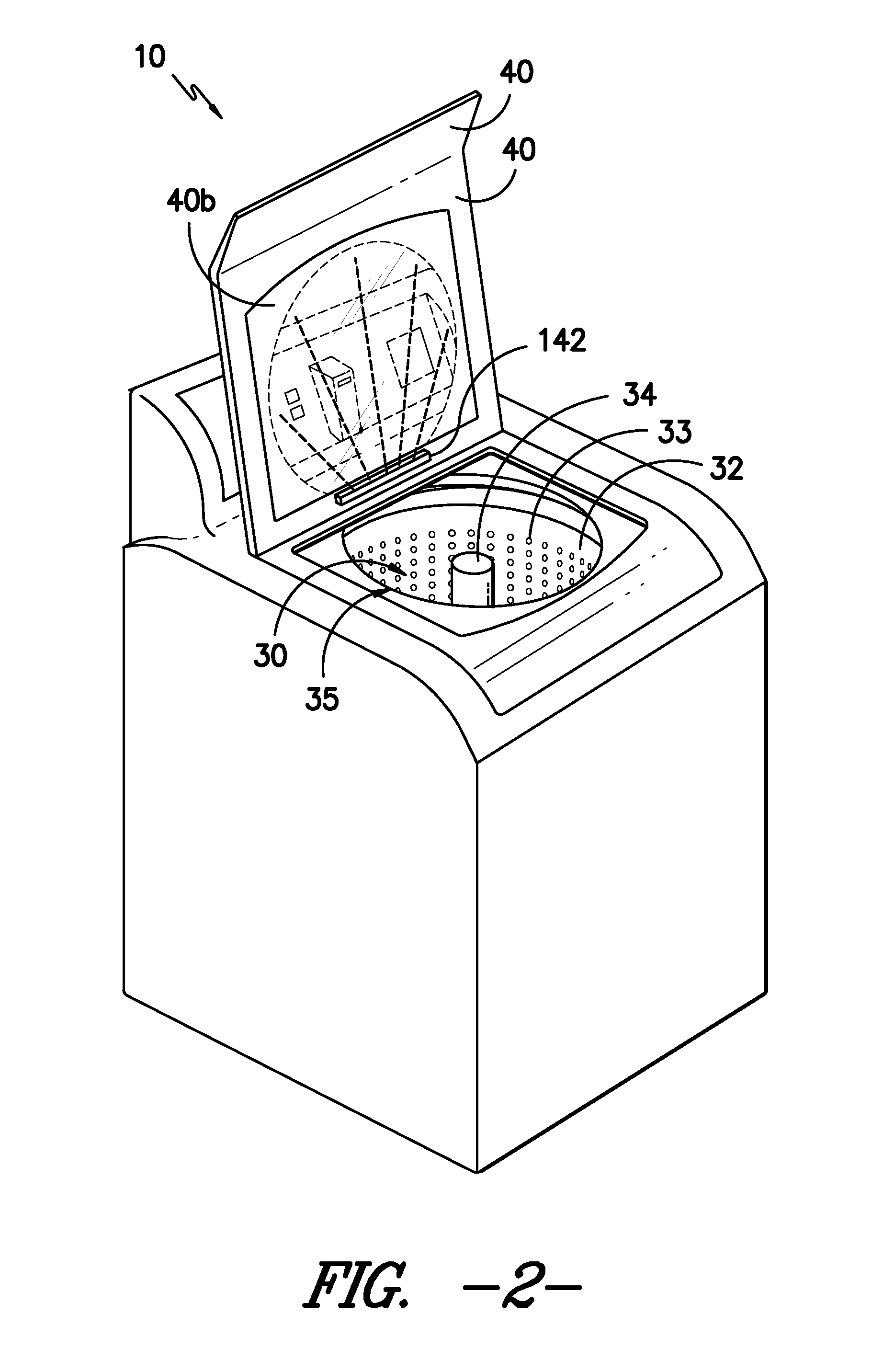
[0017]The present invention relates to a projected display, onto the surface of an appliance, of a user interface that can be utilized to make selections regarding the operation of the appliance. Where the surface is part of a door of the appliance, the user interface can be configured for display on the top surface, bottom surface, or both, of the door. The door can be constructed from an opaque material like metal or a transparent material that can have its light transmitting properties changed to make the surface non-transparent and provide a reflection of the projected display that is visible to the user. Reference now will be made in detail to embodiments of the invention, one or more examples of which are illustrated in the drawings. Each example is provided by way of explanation of the invention, not limitation of the invention. In fact, it will be apparent to those skilled in the art that various modifications and variations can be made in the present invention without depar...


PUM


Abstract

A projected display, onto the surface of an appliance, of a user interface that can be utilized to make selections regarding the operation of the appliance is described. Where the surface is part of a door of the appliance, the user interface can be configured for display on the top surface, bottom surface, or both, of the door. Such door can be constructed from a transparent material that can be transformed to provide a reflection of the projected display that is visible to the user.

Description

FIELD OF THE INVENTION[0001]The present invention relates to a projected display, onto the surface of an appliance, of a user interface that can be utilized to make selections regarding the operation of the appliance.BACKGROUND OF THE INVENTION[0002]Modern appliances such as washing machines and clothes dryers frequently provide a variety of operating options for selection by the user. For example, a washing machine may have selectable options such as the wash load size, the amount of time for the wash cycle, article types such as delicates, water temperature, and other options as well. The ability to make selections regarding the operation of the machine can be appealing to customers and influence their decisions regarding product selection.[0003]Conventionally, user selections are provided by controls mounted e.g., on a backsplash or other panel on the appliance. For example, control knobs or switches can be provided for activating various options. In addition, user interfaces in ...

Claims


Application Information

Patent Timeline
27 Dec 2012
Publication
US20120327201A1
IPC
H04N7/18; G03B21/00; D06F39/14; D06F34/20; D06F34/32
CPC
D06F39/005; G03B21/60; D06F39/14; D06F2105/58; D06F2101/00; D06F2105/44; D06F34/32; D06F2103/40
Inventors
KAPPLER, JERROD AARON; VILA, ROMAN ROMAN