Cassette jig for wafer cleaning apparatus and cassette assembly having the same

Inactive Publication Date: 2013-01-03
LG SILTRON
View PDF25 Cites 0 Cited by
  • Summary
  • Abstract
  • Description
  • Claims
  • Application Information

AI Technical Summary

Benefits of technology

[0016]According to the present invention, it can compatibly use a single cassett

Problems solved by technology

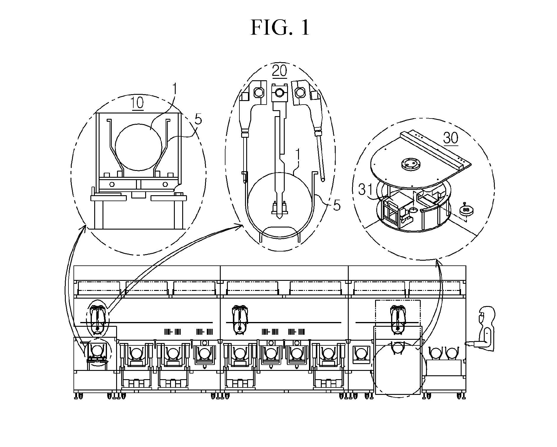
However, the bath unit 10 receiving the cassette 5 therein, an the transfer unit 20 having an arm for holding the cassette 5, and the spin dryer unit 30 having a cradle 31 where the cassette 5 is placed, each has a fixed size to handle only wafers of a prese

Method used


Image

  • Cassette jig for wafer cleaning apparatus and cassette assembly having the same
  • Cassette jig for wafer cleaning apparatus and cassette assembly having the same
  • Cassette jig for wafer cleaning apparatus and cassette assembly having the same

Examples


Example

BEST MODE

[0025]Hereinafter, preferred embodiments of the present invention will be described in detail with reference to the accompanying drawings. Prior to the description, it should be understood that the terms used in the specification and the appended claims should not be construed as limited to general and dictionary meanings, but interpreted based on the meanings and concepts corresponding to technical aspects of the present invention on the basis of the principle that the inventor is allowed to define terms appropriately for the best explanation. Therefore, the description proposed herein is just a preferable example for the purpose of illustrations only, not intended to limit the scope of the invention, so it should be understood that other equivalents and modifications could be made thereto without departing from the spirit and scope of the invention.

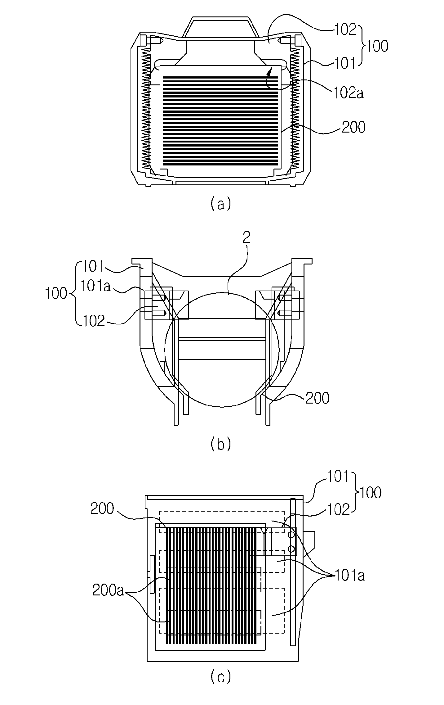
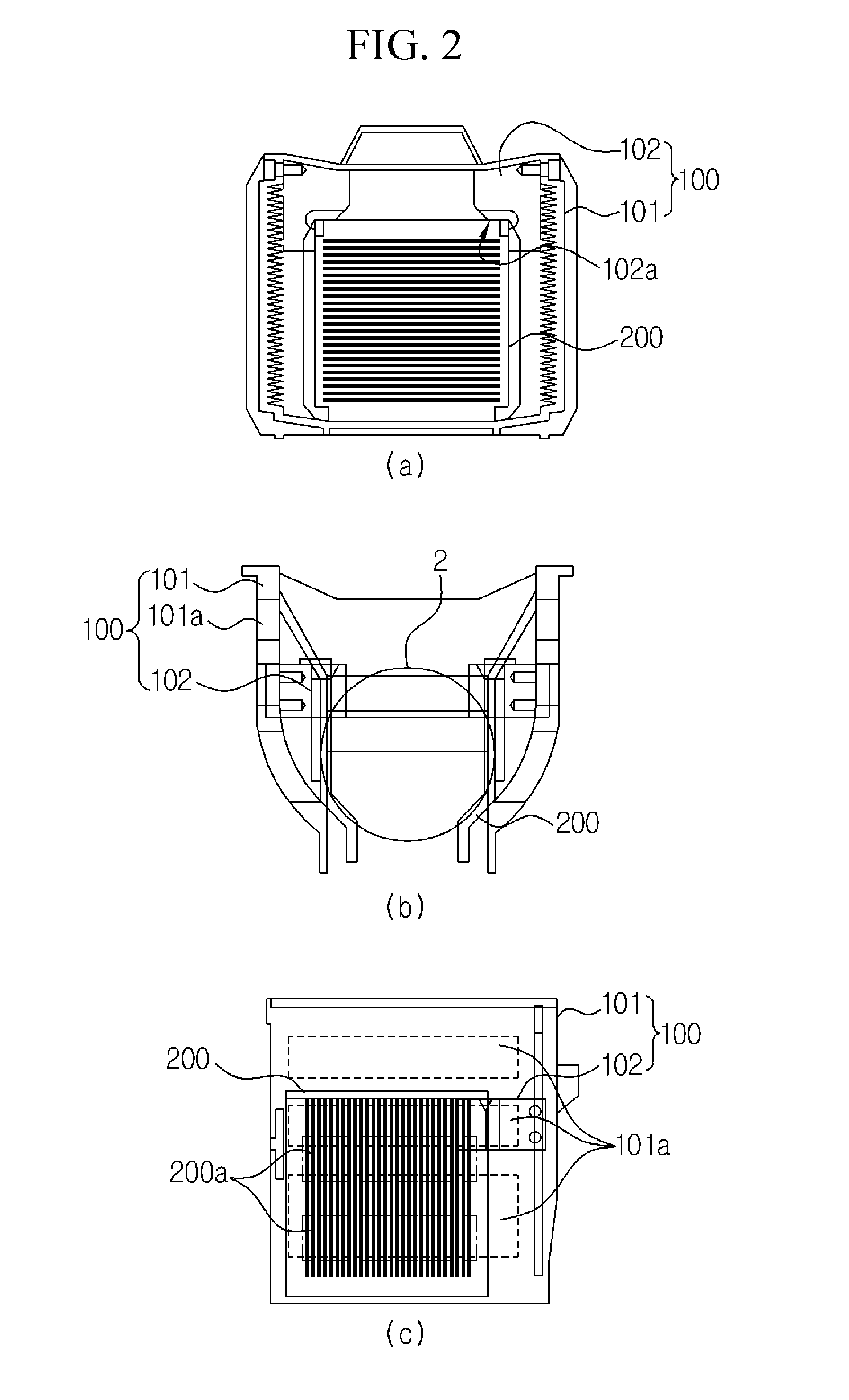
[0026]FIGS. 2 and 3 each is a view illustrating a configuration of a cassette assembly for a wafer cleaning apparatus accordi...


PUM


Abstract

A cassette jig for a wafer cleaning apparatus is provided, comprising a jig body having an inner space designed to receive a first wafer therein; and a guide member mounted in the jig body and operative to guide a cassette to be installed in the jig body, the cassette having an inner space designed to receive a second wafer of a relatively smaller diameter than the first wafer therein.

Description

TECHNICAL FIELD[0001]The present invention relates to a cassette used in a wafer cleaning apparatus, and more particularly, to a cassette jig that is applicable to a wafer cleaning apparatus for cleaning wafers of various sizes, and a cassette assembly having the same.CROSS-REFERENCE TO RELATED APPLICATION[0002]This application claims priority to Korean Patent Application No. 10-2010-0006096 filed in Republic of Korea on Jan. 22, 2010, the entire contents of which are incorporated herein by reference.BACKGROUND ART[0003]In a semiconductor wafer fabrication process, a cleaning process is a process for cleaning the surface of a wafer by removing various kinds of particles or metal contaminants remaining on the surface of the wafer.[0004]Conventionally, the wafer cleaning process sequentially cleans and dries wafers 1 by means of a wafer cleaning apparatus, as shown in FIG. 1. Referring to FIG. 1, the wafer cleaning apparatus comprises a bath unit 10 for receiving a cleaning solution t...

Claims


Application Information

Patent Timeline
IPC IPC(8): H01L21/673B08B13/00
CPCH01L21/6732H01L21/67326
Inventor PARK, JAE-HYUNCHOI, CHUNG-HYO
Owner LG SILTRON
Why Eureka
Try Eureka