Process Cartridge

Active Publication Date: 2013-02-28
BROTHER KOGYO KK
View PDF1 Cites 52 Cited by
  • Summary
  • Abstract
  • Description
  • Claims
  • Application Information

AI Technical Summary

Benefits of technology

[0006]In view of the above, it would be desirable to provide a process cartridge, which

Problems solved by technology

This leads to poor operabili

Method used


Image

  • Process Cartridge
  • Process Cartridge
  • Process Cartridge

Examples


first embodiment

[0017]A detailed description will be given of a first embodiment of the present invention with reference to the accompanying drawings.

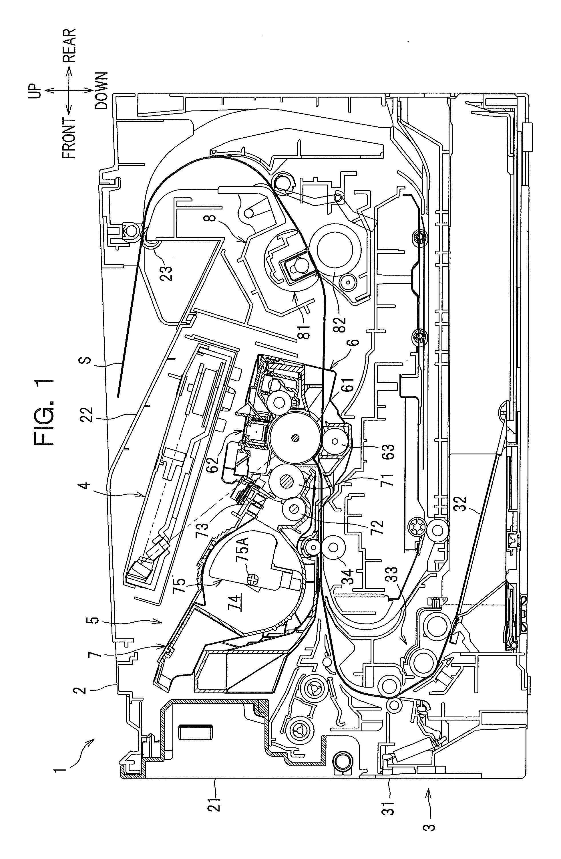
[0018]In the following description, a general arrangement of a laser printer comprising a process cartridge according to the first embodiment will be described, and thereafter characteristic features of the present invention will be described in detail.

[0019]In the following description, the direction is designated as from the viewpoint of a user who is using (operating) the laser printer. To be more specific, in FIG. 1, the left-hand side of the drawing sheet corresponds to the “front” side of the laser printer, the right-hand side of the drawing sheet corresponds to the “rear” side of the laser printer, the front side of the drawing sheet corresponds to the “right” side of the laser printer, and the back side of the drawing sheet corresponds to the “left” side of the laser printer. Similarly, the direction extending from top to bottom of the drawing...

second embodiment

[0055]A detailed description will be given of a second embodiment of the present invention with reference to the accompanying drawings.

[0056]Whereas the locking member and the retaining member are provided discretely in the first embodiment, the locking member and the retaining member are formed as a single part in this embodiment.

[0057]In this embodiment, parts similar to those previously described in the first embodiment are denoted by the same reference numerals and detailed description thereof will be omitted.

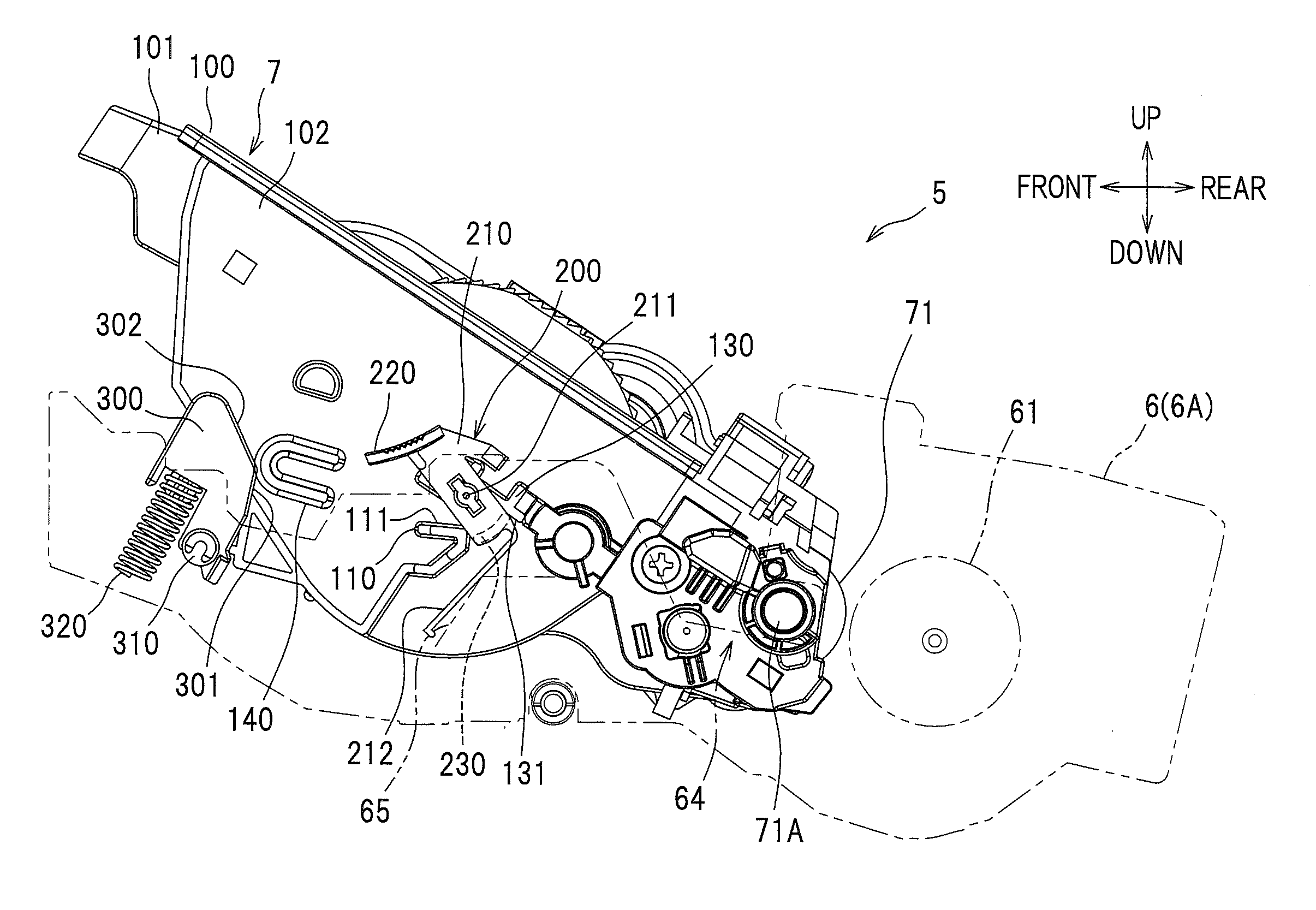
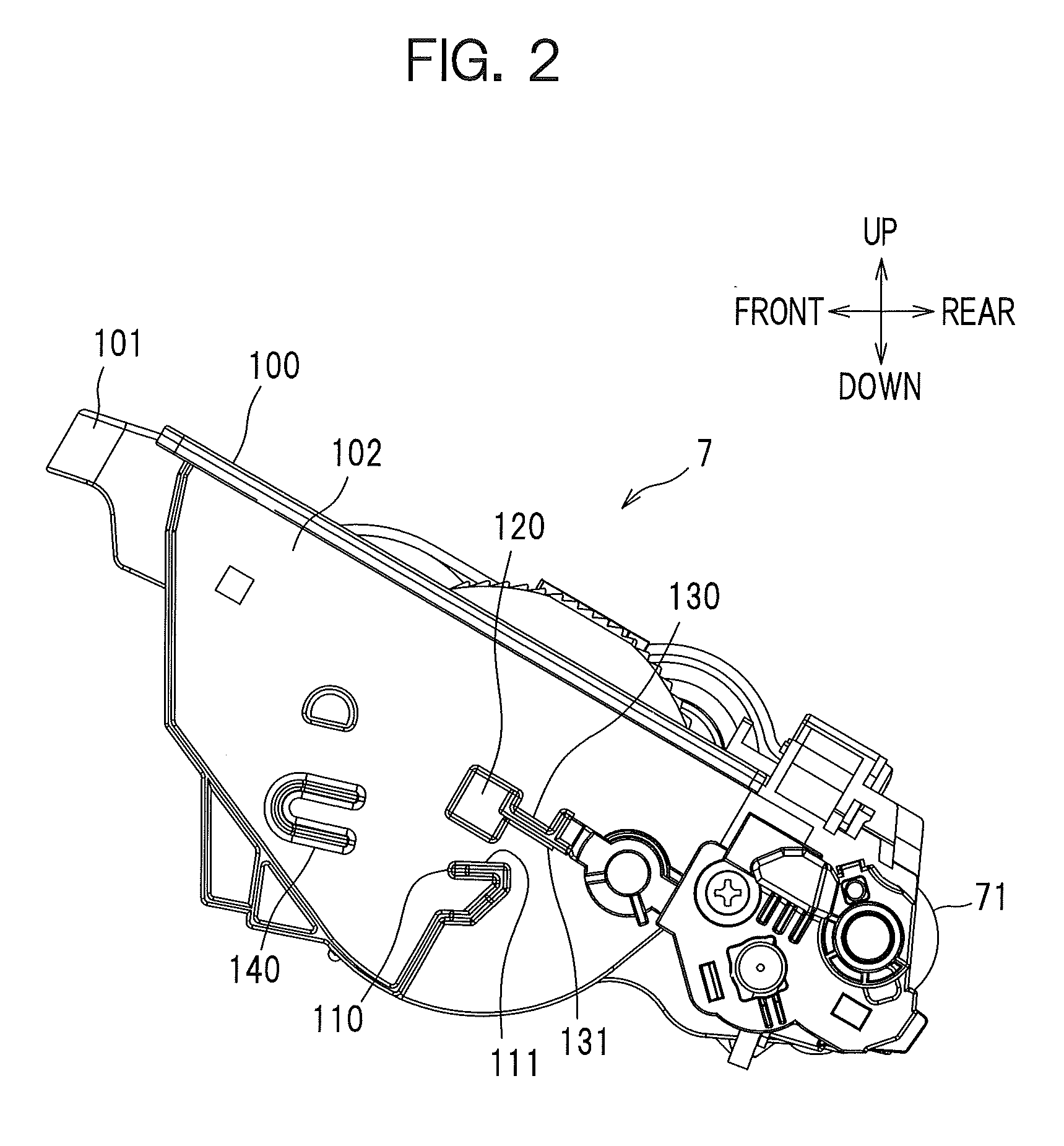
[0058]As seen in FIG. 7A, a locking rib 110 and a lifting rib 130 are formed on a side wall of the development cartridge 7.

[0059]The locking rib 110 is disposed below a locking member 400 to be described later. The locking rib 110 has a surface 111 which faces upward.

[0060]The lifting rib 130 is disposed above the locking member 400 to be described later. The lifting rib 130 has a contacting surface 131 which faces diagonally downward and frontward.

[0061]The locking member ...


PUM


Abstract

A process cartridge includes: a drum cartridge including a photoconductor; a development cartridge configured to be detachably attached to the drum cartridge and including a developer carrying member for supplying developer to the photoconductor; a locking member provided on the drum cartridge and configured to be switchable between a locking position in which the development cartridge attached to the drum cartridge is in a locked state and restrained from being moved in a removing direction in which the development cartridge is removed from the drum cartridge and a lifting position in which the locked state is released and the development cartridge is movable in the removing direction, and a retaining member configured to retain the development cartridge which has been moved from the locked state in the removing direction by switching the locking member from the locking position to the lifting position.

Description

CROSS-REFERENCE TO RELATED APPLICATION(S)[0001]This application claims priority from Japanese Patent Application No. 2011-186889 filed on Aug. 30, 2011, the disclosure of which is incorporated herein by reference in its entirety.TECHNICAL FIELD[0002]The present invention relates to a process cartridge comprising a drum cartridge and a development cartridge detachably attached to the drum cartridge.BACKGROUND ART[0003]Conventionally, a process cartridge is known in the art, which includes a drum cartridge and a development cartridge detachably attached to the drum cartridge. To be more specific, this type of process cartridge includes a lock lever swingably supported on the drum cartridge.[0004]The lock lever contacts with a part of the development cartridge in a state in which the development cartridge is attached to the drum cartridge, so that the development cartridge is locked to the drum cartridge to prevent disengagement of the development cartridge from the drum cartridge. Whe...

Claims


Application Information

Patent Timeline
IPC IPC(8): G03G21/18
CPCG03G21/1821G03G15/0867G03G15/0865G03G21/1842
Inventor FUKAMACHI, YASUO
Owner BROTHER KOGYO KK
Why Eureka
Try Eureka