
Image forming apparatus, computer-readable medium and data processing method

Inactive Publication Date: 2009-06-25
KONICA MINOLTA BUSINESS TECH INC
View PDF3 Cites 1 Cited by
  • Summary
  • Abstract
  • Description
  • Claims
  • Application Information

AI Technical Summary

Benefits of technology

[0010]The present invention has been made in consideration of the above problems, and it is one of main objects to efficiently use a storage medium and to ease trouble of operation by the user in an image forming apparatus to form an image based on an XPS file.

Problems solved by technology

Incidentally, storage capacity of a storage medium is limited, and various efforts are made to use the limited storage capacity efficiently.
However, with the technique described above, since character of high usage frequency is preset manually, character of high usage frequency needs to be set again newly according to situation of various image forming, which is troublesome.
Also, since the usage frequency is set manually, there is a possibility that error in the setting may occur.

Method used


Image

  • Image forming apparatus, computer-readable medium and data processing method
  • Image forming apparatus, computer-readable medium and data processing method
  • Image forming apparatus, computer-readable medium and data processing method

Examples


first embodiment

[0031]In the following, a first embodiment of an image forming apparatus according to the present invention will be described.

[System Configuration of Image Forming System]

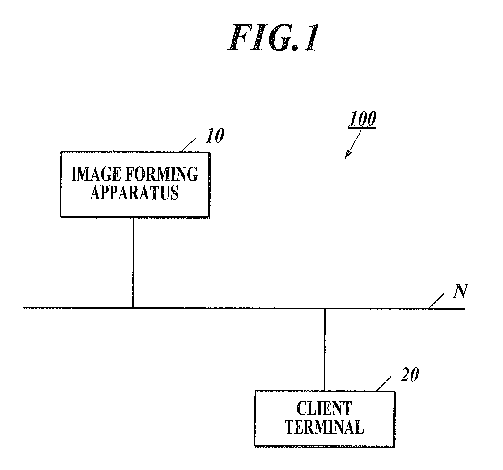
[0032]FIG. 1 shows a system configuration of an image forming system 100. As shown in FIG. 1, the image forming system 100 is composed of an image forming apparatus 10 and client terminal 20, and each apparatus is connected to each other through a communication network N in a state capable of performing data communications.

[0033]The image forming apparatus 10 is the so-called Multi-Function Peripheral (MFP) including a copy function, an image reading function, and a printer function, and forms an image on a sheet based on a print job (print instruction) sent from the client terminal 20, image data read by an image reading section, such as a scanner, provided in the image forming apparatus 10, and the like.

[0034]The client terminal 20 is the so-called personal computer, and has the function of sending a print job t...

second embodiment

[0094]In the following, a second embodiment of an image forming apparatus according to the present invention will be described. Incidentally, different point between the second embodiment and the first embodiment is the processing content of the XPS file decompression processing. In the XPS file decompression processing of the second embodiment, the CPU 11 selects the storage section to store the data-decompressed individual file based on attribute (type of individual file such as individual file showing page configuration information, individual file of font data, etc.) of the individual file and usage frequency.

[XPS File Decompression Processing]

[0095]In the following, specific processing content of the XPS file decompression processing (step S3 shown in FIG. 6) is described with reference to FIG. 11. FIG. 11 is a flowchart showing the XPS file decompression processing.

[0096]As shown in FIG. 11, the CPU 11 extracts the individual file stored in the XPS file (step S401). Then, the ...


PUM


Abstract

Disclosed is an image forming apparatus to form an image based on an XPS file including, a plurality of storage sections each of which has a different free storage space and a different access speed; and a control section to refer to information concerning usage frequency of each individual file stored in the XPS file to select the storage section to store the individual file subjected to a data decompression, to data-decompress the individual file, and to store the data-decompressed individual file in the selected storage section.

Description

CROSS-REFERENCE TO RELATED APPLICATIONS[0001]The present U.S. Patent Application claims priority under the Paris Convention of Japanese Patent Application No. 2007-332547 filed on Dec. 25, 2007 to the Japanese Patent Office, which shall be a basis for correcting mistranslations.BACKGROUND[0002]1. Field of the Invention[0003]The present invention relates to an image forming apparatus, computer-readable medium and data, processing method.[0004]2. Description of Related Art[0005]In recent years, an image forming system in which a data processing apparatus such as a personal computer (PC) with a printer driver installed controls an image forming apparatus through a communication network such as a local area network (LAN), has become widely used.[0006]Moreover, Microsoft Corporation announced an electronic document standard called an extensible markup language (XML) paper specification (XPS) standard at the end of 2006. A file of an electronic document in conformity to the XPS standard (...

Claims


Application Information

Patent Timeline
IPC IPC(8): G06F3/12
CPCH04N1/00832H04N1/32128H04N1/32358H04N2201/0094H04N2201/3283H04N2201/3232H04N2201/3242H04N2201/3243H04N2201/325H04N2201/3202
Inventor OZAWA, MASAHIROTANAKA, YOSHINORIAKIYAMA, FUMIHITOKUROKI, JUNNOGAWA, HIROSHIAOYAMA, YASUFUMI
Owner KONICA MINOLTA BUSINESS TECH INC
Learn More