Eureka AIR delivers breakthrough ideas for toughest innovation challenges, trusted by R&D personnel around the world.

Determining Coefficients For Digital Low Pass Filter Given Cutoff And Boost Values For Corresponding Analog Version

a low-pass filter and coefficient technology, applied in the field of read channels, can solve the problems of increasing the difficulty of building analog circuits, such as ctf filters, to meet the demanding performance specifications, and introduce noise and other distortions into the read signal

Active Publication Date: 2013-02-28
AVAGO TECH INT SALES PTE LTD
View PDF4 Cites 4 Cited by
  • Summary
  • Abstract
  • Description
  • Claims
  • Application Information

AI Technical Summary

Benefits of technology

The patent describes methods and devices for determining coefficients for a digital low pass filter based on the properties of its analog version. This allows for the creation of filters with specific performance requirements. The coefficients are calculated by obtaining cutoff and boost values for the analog version and using them to generate a transfer function in the frequency domain. This transfer function is then transformed to a continuous time representation to obtain the coefficients for the digital low pass filter. The number of coefficients is optionally truncated to a maximum value, and the digital low pass filter can perform various functions in the digital domain that were previously performed in the analog domain. The technical effect of this patent is the ability to create digital filters with precise performance requirements.

Problems solved by technology

Read heads and magnetic media introduce noise and other distortions into the read signal.
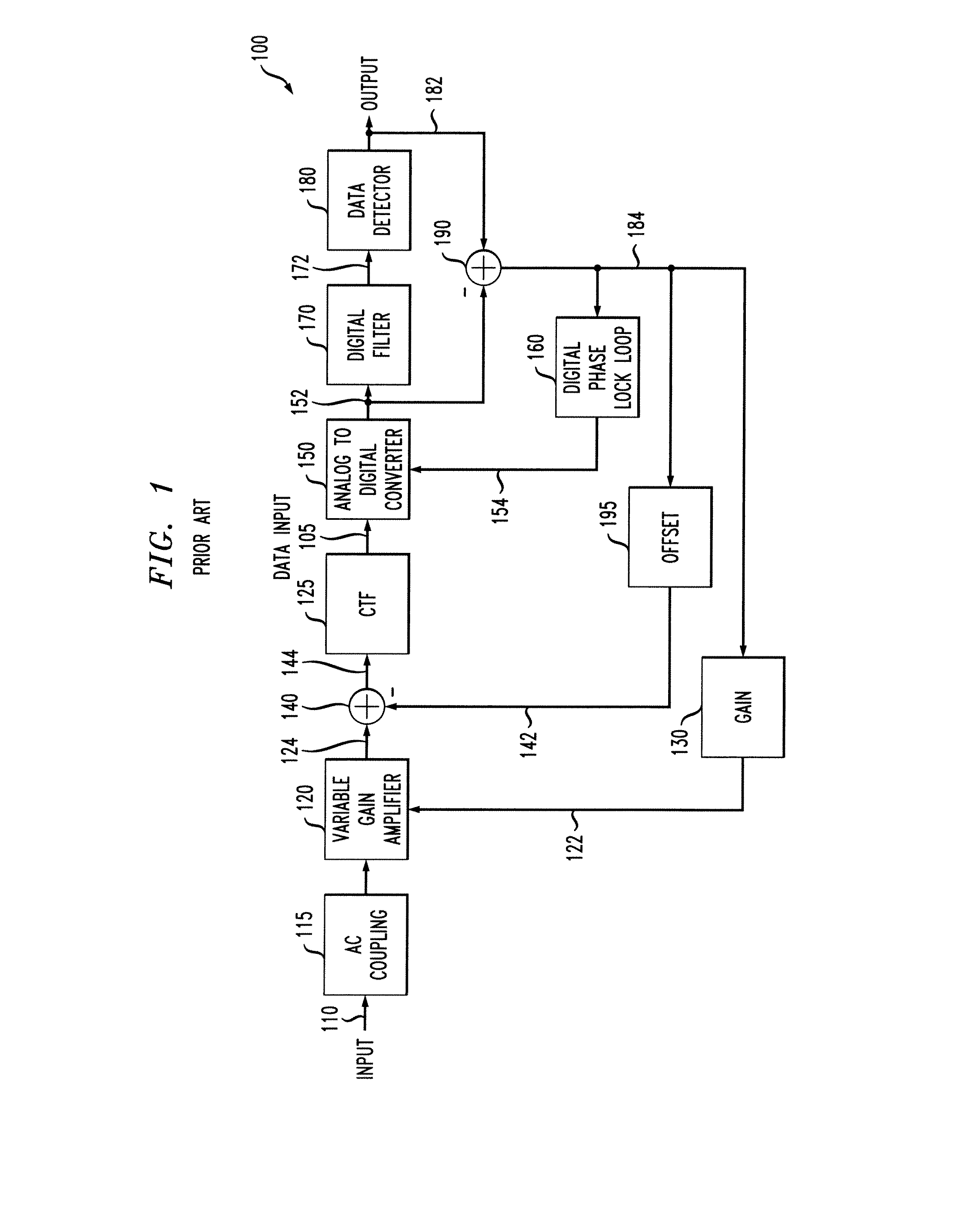
As process technology gets smaller and data rates increase, it becomes increasingly challenging to build analog circuits, such as the CTF filters, that meet the demanding performance specifications of read channels.

Method used


Image

  • Determining Coefficients For Digital Low Pass Filter Given Cutoff And Boost Values For Corresponding Analog Version
  • Determining Coefficients For Digital Low Pass Filter Given Cutoff And Boost Values For Corresponding Analog Version
  • Determining Coefficients For Digital Low Pass Filter Given Cutoff And Boost Values For Corresponding Analog Version

Examples


Embodiment Construction

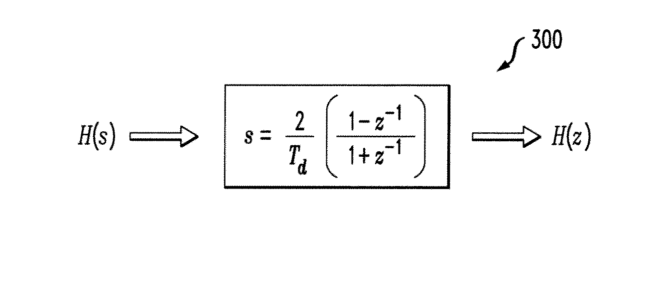
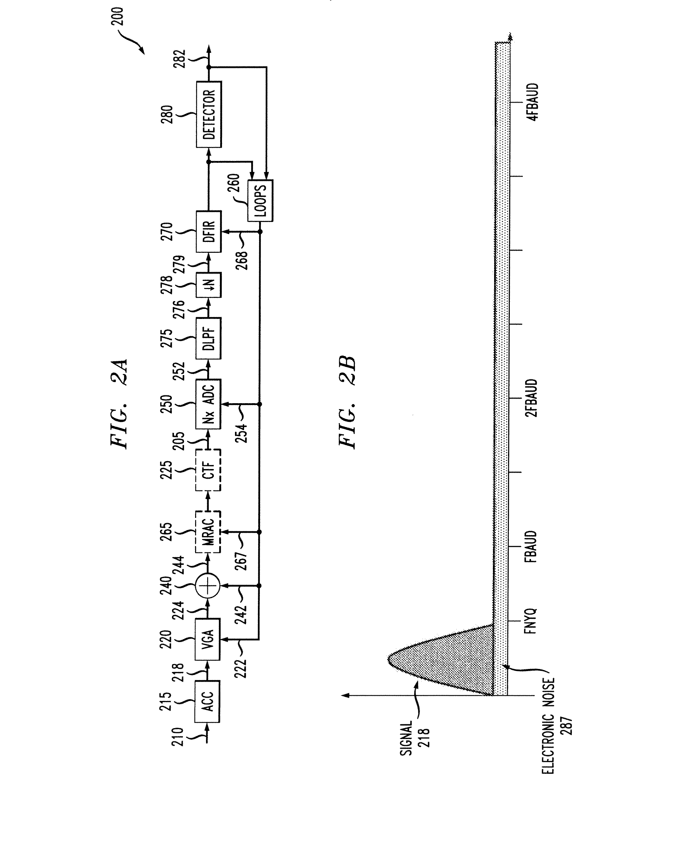
[0028]The present invention provides improved techniques for determining coefficients for a digital low pass filter given cutoff and boost values for a corresponding analog version of the digital low pass filter. While the present invention is illustrated in the exemplary context of digital low pass filters employed in a read channel, the present invention can be employed to determine coefficients for any digital low pass filters, as would be apparent to a person of ordinary skill in the art. In the exemplary embodiment, the disclosed techniques are employed in an exemplary read channel that employs an oversampled ADC that generates a plurality of digital samples per bit period. In this manner, the CTF circuit can be simplified by transferring at least a portion of the equalization process to the digital domain. The oversampled ADC allows a portion of the filtering to be performed in the analog domain and a portion of the filtering to be performed in the digital domain. For example,...


PUM


Abstract

Methods and apparatus are provided for determining coefficients for a digital low pass filter, given cutoff and boost values for a corresponding analog version of the digital low pass filter. Coefficients are determined for a digital low pass filter by obtaining cutoff and boost values for a corresponding analog version of the digital low pass filter; and determining the coefficients for the digital low pass filter based on the obtained cutoff and boost values. The coefficients can be determined, for example, by generating a transfer function, H(s), for the corresponding analog version using the obtained cutoff and boost values: transforming the transfer function, H(s), to a frequency domain characterization, H(z), using one or more bilinear transforms to obtain a plurality of coefficients for an infinite impulse response (IIR) filter; generating the IIR filter using the plurality of coefficients for the IIR filter; and applying an impulse to the IIR filter to obtain the one or more coefficients for the digital low pass filter. In another variation, the coefficients are pre-computed and obtained from a look-up table.

Description

CROSS-REFERENCE TO RELATED APPLIATIONS[0001]The present invention is related to United States Patent Application entitled “Read Channel With Oversampled Analog to Digital Conversion,” United States Patent Application entitled “Read Channel With Selective Oversampled Analog to Digital Conversion,” and United States Patent Application entitled “Read Channel With Oversampled Analog to Digital Conversion and Parallel Data Detectors,” each filed contemporaneously herewith and incorporated by reference herein.FIELD OF THE INVENTION[0002]The present invention relates generally to read channels and, more particularly, to techniques for determining one or more coefficients for a digital low pass filter that may be used, for example, in such read channels.BACKGROUND OF THE INVENTION[0003]A magnetic recording read channel converts an analog read signal into an estimate of the user data that was recorded on a magnetic medium. Read heads and magnetic media introduce noise and other distortions i...

Claims


Application Information

Patent Timeline
IPC IPC(8): G06F17/10
CPCG11B20/10046H03H17/0294H03H17/04G11B2220/2508G11B20/10018G11B20/10027H03H17/0685
Inventor ARAVIND, NAYAK RATNAKARHARATSCH, ERICH F.
Owner AVAGO TECH INT SALES PTE LTD
Why Eureka
Eureka Blog
Learn More