Fan assembly with backflow preventing structure

a technology of backflow prevention and fan assembly, which is applied in the direction of electrical apparatus construction details, instruments, transportation and packaging, etc., can solve the problems of hot spots, failure to cool the component of the computer, and interference with the air flow through the operating fan

Inactive Publication Date: 2013-03-07
HONG FU JIN PRECISION IND (SHENZHEN) CO LTD +1
View PDF4 Cites 17 Cited by
  • Summary
  • Abstract
  • Description
  • Claims
  • Application Information

AI Technical Summary

Problems solved by technology

Although a fan-based system provides effective component cooling, it has drawbacks.
For example, if the fan fails or locks up, there will a failure to cool the component of the computer.
However, the airflow past the components closest to the failing fan may be considerably reduced, or may even be reversed due to back pressure, thus creating hot spots and interfering with the air flow through the operating fans.

Method used


Image

  • Fan assembly with backflow preventing structure
  • Fan assembly with backflow preventing structure
  • Fan assembly with backflow preventing structure

Examples


Embodiment Construction

[0017]Embodiments of the present disclosure will now be described in detail with reference to the accompanying drawings.

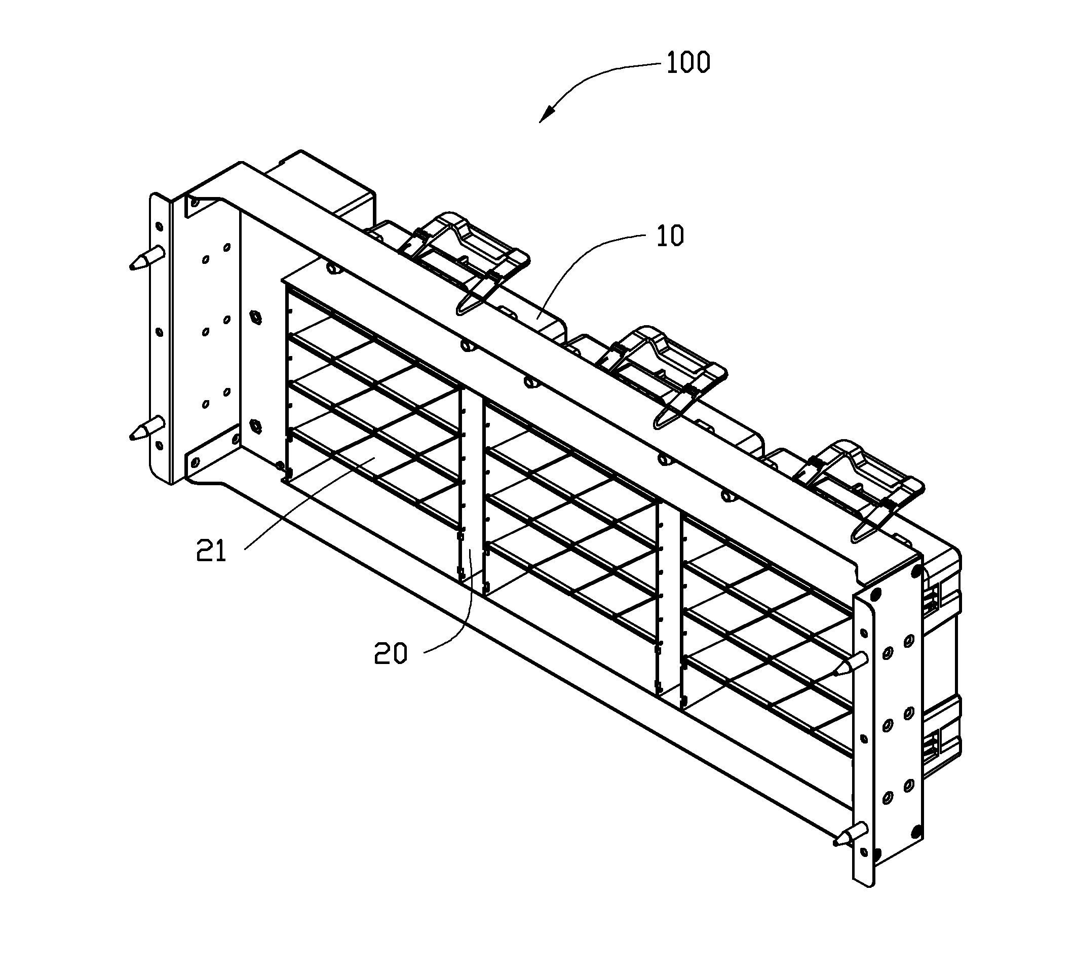
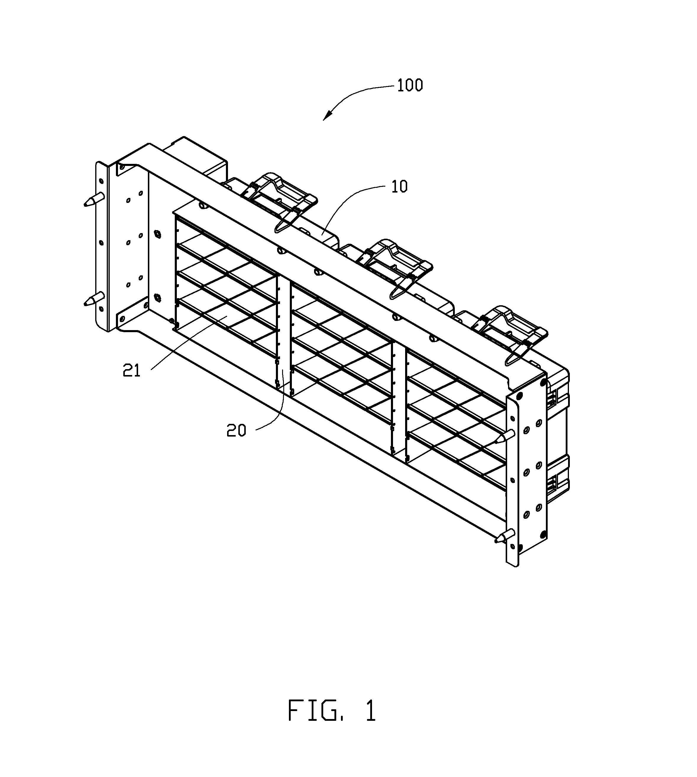
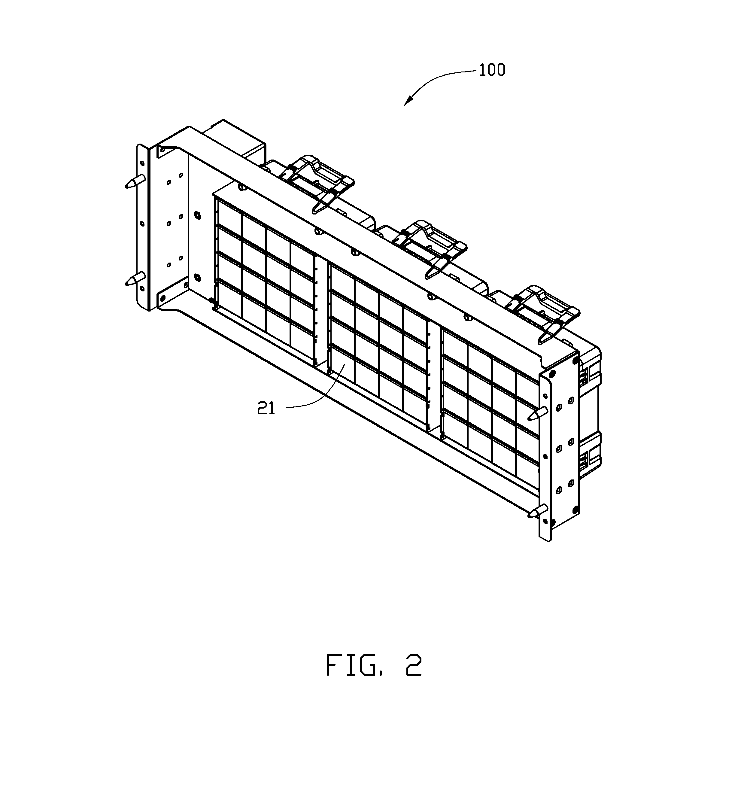
[0018]Referring to FIGS. 1 and 2, a fan assembly 100 for use in a computer system includes a fan 10, a frame 22 (FIG. 5) fixed to the fan 10, and a number of louvers 21 rotatably connected to the frame 22. When the fan 10 is in operation, the louvers 21 are driven by the air pressure established by the fan 10 to rotate to an open position (FIG. 1) in which air flow can pass through the fan 10. When the fan 10 is not in operation, the louvers 21 rotate to a closed position (FIG. 2) under the force of their own gravity. The louvers 21 in the closed position substantially form a shield and block airflow to pass through fan 10.

[0019]FIG. 3 shows a computer system 200 including two conventional fans 10a. When one fan 10a fails, the air moving out of the computer system 200 via the remaining functioning fan 10a may flow back into the computer system 200 through the faile...


PUM


Abstract

A fan assembly for a computer system includes a fan and a frame connected to the fan. A number of louvers are rotatably connected to the frame and are capable of rotating between an open position in response to air pressure established by the fan in which air is permitted to flow through the fan, and a closed position under a force of gravity when the fan is inoperable in which the louvers block the air to flow through the fan. Each louver defines at least one groove along a width direction, and each of the at least one groove allows two portions at opposite sides to be broken off from each other.

Description

BACKGROUND[0001]1. Technical Field[0002]The present disclosure relates to cooling fans, and particularly, to a fan assembly for a computer system with backflow preventing structure.[0003]2. Description of Related Art[0004]One of the most effective techniques of dissipating heat from a component of a computer is to directly apply a relatively high velocity airflow across the surface of the component. Although a fan-based system provides effective component cooling, it has drawbacks. For example, if the fan fails or locks up, there will a failure to cool the component of the computer. One solution in this regard is to incorporate a secondary, redundant fan to protect the component of the computer.[0005]Nonetheless, in those multi-fan arrangements, each fan moves a portion of the air being used for cooling, and the design is usually such that the total cooling capacity of the fans is greater than minimally necessary to cool the computer. Thus if a single fan fails, the airflow created ...

Claims


Application Information

Patent Timeline
Patent Type & Authority Applications(United States)
IPC IPC(8): F15D1/00
CPCH05K7/20181G06F1/20Y10T137/3149
Inventor TANG, XIAN-XIU
Owner HONG FU JIN PRECISION IND (SHENZHEN) CO LTD
Why Eureka
Try Eureka