
Maintenance apparatus of electronic device, maintenance method of electronic device, and non-transitory computer readable medium storing program

Active Publication Date: 2013-03-07
NEC PLATFORMS LTD
View PDF3 Cites 2 Cited by
  • Summary
  • Abstract
  • Description
  • Claims
  • Application Information

AI Technical Summary

Benefits of technology

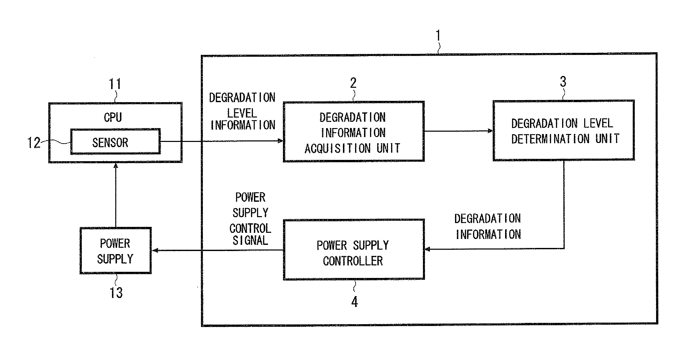
[0015]A first exemplary aspect of the present invention is a maintenance apparatus of an electronic device including: a degradation information acquisition unit that acquires degradation information from a sensor integrated in a CPU when the CPU performs a normal operation, the degradation information varying according to degradation of the CPU; a

Problems solved by technology

One known cause that leads to degradation of the CPU is hot carrier effects caused by time degradation of a semiconductor device such as a transistor.
However, such a treatment

Method used


Image

  • Maintenance apparatus of electronic device, maintenance method of electronic device, and non-transitory computer readable medium storing program
  • Maintenance apparatus of electronic device, maintenance method of electronic device, and non-transitory computer readable medium storing program
  • Maintenance apparatus of electronic device, maintenance method of electronic device, and non-transitory computer readable medium storing program

Examples


Example

Second Exemplary Embodiment

[0047]FIG. 6 shows a configuration of a maintenance apparatus 31 of an electronic device according to a second exemplary embodiment of the present invention. The maintenance apparatus 31 includes a scheduler controller 32 in addition to the degradation information acquisition unit 2, the degradation level determination unit 3, and the power supply controller 4 that are stated above.

[0048]The scheduler controller 32 controls a job scheduler 35 included in the electronic device. The scheduler controller 32 may be formed by collaboration of a microprocessor, a control / operation program and the like, as is similar to the degradation information acquisition unit 2, the degradation level determination unit 3, and the power supply controller 4. The scheduler controller 32 controls the job scheduler 35 so that the processing load of the CPU 11 decreases with increasing the degradation level.

[0049]According to the configuration stated above, the progress of the deg...

Example

Third Exemplary Embodiment

[0059]FIG. 10 shows a configuration of a maintenance apparatus 51 of an electronic device according to a third exemplary embodiment of the present invention. The maintenance apparatus 51 is different from the maintenance apparatus 31 according to the second exemplary embodiment in that the maintenance apparatus 51 includes a control selection unit 52.

[0060]When the target value of the power supply voltage calculated by the power supply controller 4 according to the degradation level is larger than an upper-limit value of the power supply voltage determined according to a power supply mode such as a power saving mode, the control selection unit 52 does not perform control by the power supply controller 4 (control to increase the power supply voltage according to the increase in the degradation level) but performs control by the scheduler controller 32 (control to reduce the processing load of the CPU 11 according to the degradation level). The control select...


PUM


Abstract

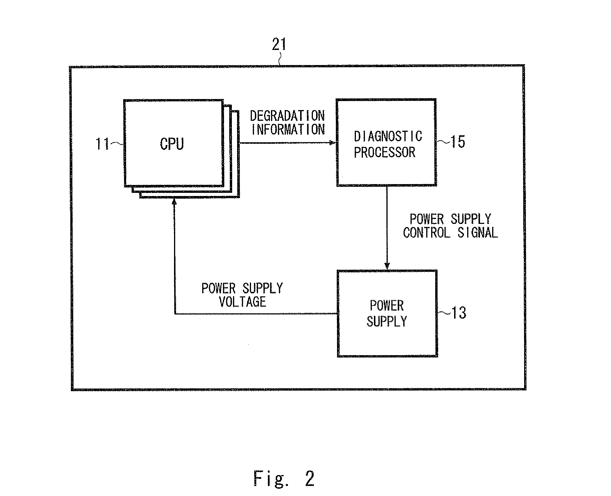
Provided is a technique of compensating time degradation of a CPU and maintaining performance of an electronic device without disturbing a normal operation of the electronic device. A maintenance apparatus includes: a degradation information acquisition unit that acquires degradation information from a sensor circuit integrated in a CPU when the CPU performs a normal operation, the degradation information varying according to degradation of the CPU; a degradation level determination unit that determines a degradation level based on the degradation information, the degradation level indicating a degree of progression of degradation of the CPU; and a power supply control unit that controls a power supply to increase a power supply voltage applied to the CPU with increasing the degradation level.

Description

INCORPORATION BY REFERENCE[0001]This application is based upon and claims the benefit of priority from Japanese patent application No. 2011-194241, filed on Sep. 6, 2011, the disclosure of which is incorporated herein in its entirety by reference.BACKGROUND OF THE INVENTION[0002]1. Technical Field[0003]The present invention relates to a maintenance apparatus to maintain performance of an electronic device, and more specifically, to a maintenance apparatus that deals with time degradation of a central processing unit (CPU).[0004]2. Background Art[0005]Performance of an electronic device such as a computer is degraded according to degradation of a CPU that is built therein. One known cause that leads to degradation of the CPU is hot carrier effects caused by time degradation of a semiconductor device such as a transistor.[0006]Japanese Unexamined Patent Application Publication No. 2010-203816 discloses a degradation diagnosis apparatus that detects degradation (correlative degradation...

Claims


Application Information

Patent Timeline
IPC IPC(8): G06F11/30
CPCG06F11/3024G06F11/3093G06F11/3062
Inventor ISHIHARA, SHINGO
Owner NEC PLATFORMS LTD
Learn More