Shackle Assembly

a technology of assembly and chain, which is applied in the direction of chain elements, shackles, driving chains, etc., can solve the problems of reducing the accuracy of measuring the load applied, and achieve the effect of accurate manufacturing methods and reliably repeatable creation

Active Publication Date: 2013-03-21
TECSIS
View PDF6 Cites 11 Cited by
  • Summary
  • Abstract
  • Description
  • Claims
  • Application Information

AI Technical Summary

Benefits of technology

[0025]Preferably, the shackle body may be formed by an investment casting process using stainless steel. The stainless steel may be of Type 17-4 or other suitable material, and may preferably have a hardness of h900 or other suitable hardness. In this investment casting method, one or more wax models of the shackle are formed, for example, by wax casting or the like. These wax models are packed into a ceramic and/or sand cover. The ceramic/sand material is fired to form th

Problems solved by technology

Furthermore, the standard shackle is usually a forged product, in which dimensions

Method used


Image

  • Shackle Assembly
  • Shackle Assembly
  • Shackle Assembly

Examples


first embodiment

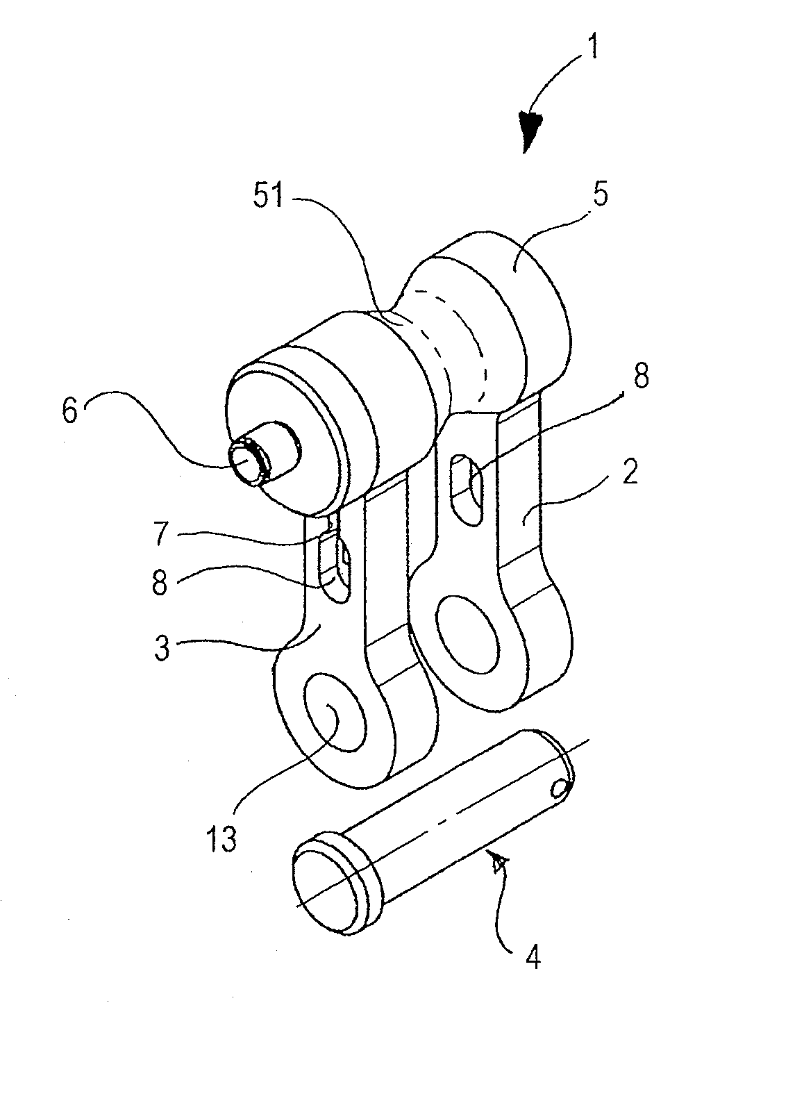
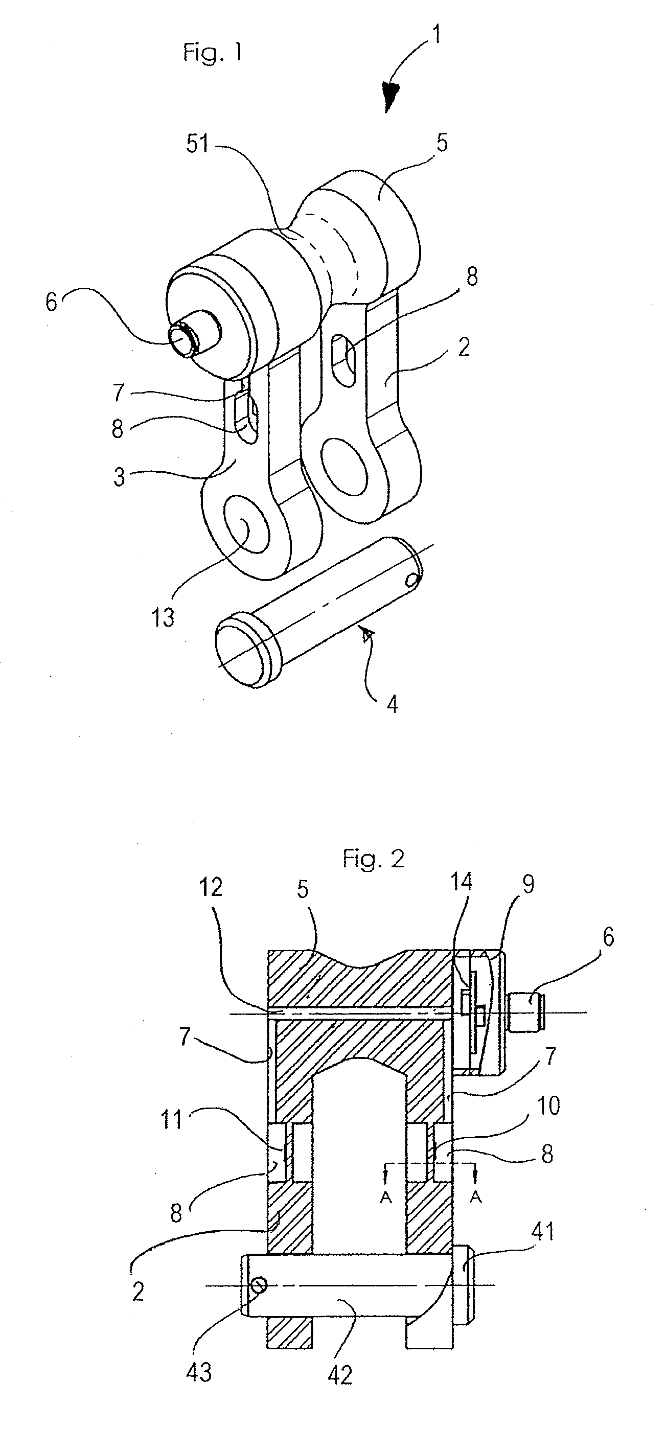
[0032]a shackle assembly in which a strain sensing elements are provided in the shackle arms is shown in FIGS. 1 to 3. According to FIG. 1, the shackle body 1 includes shackle arms 2 and 3 and a bridge portion 5 which connects the shackle arms 2, 3 in a rigid manner. Each shackle arm 2, 3 has a pocket 8 formed therein which forms a cavity for accommodating one or more strain sensing element(s) (not shown for clarity), and further has a hole 13 for receiving a shackle pin 4. In the shackle arm 3 there is shown a slit 7 which extends from the pocket 8 in the direction of the bridge portion 5 of the shackle body 1. The bridge portion 5 has a reduction of outer diameter in its middle portion 51, so that a ring, a thimble or a chain link is guided into a load bearing position when load is applied to the shackle assembly. The bridge portion may also be described as having a shape of a spool which is formed by two truncated cones which are connected to each other at their tip. In this way,...

second embodiment

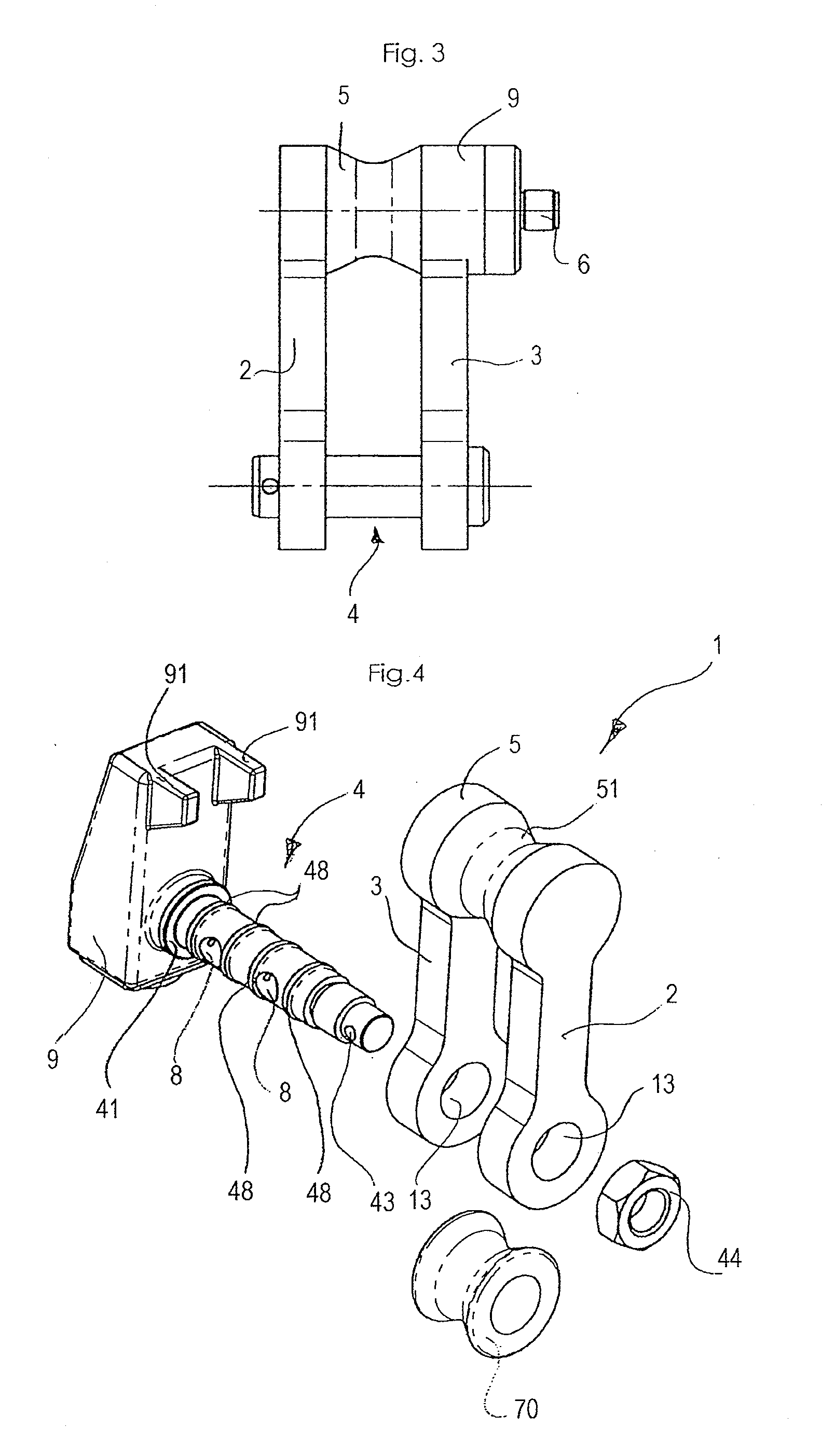
[0039]FIG. 4 depicts a schematic perspective view of a shackle assembly in accordance with the present invention. It is noted that the same reference signs are used for the elements which are functionally the same as the corresponding elements described above with reference to FIGS. 1 to 3. Accordingly, the description of these elements applies here in analogous manner.

[0040]The shackle assembly of FIG. 4 has a shackle body 1 having two shackle arms 2 and 3 which are, at one end thereof, rigidly connected to each other by a bridge portion 5. The bridge portion 5 has a reduced diameter portion 51 for guiding the load application element, like a ring, a thimble, a chain link or the like into a central position at the bridge portion 5. At the end opposite to the bridge portion, receiving holes 13 are provided which holes are arranged for receiving a shackle pin 4 in a load bearing manner. The shackle arms have a rectangular cross-section, but here any other shape may be used in this em...


PUM


Abstract

A shackle assembly includes a shackle body having two shackle arms extending from a bridge portion which is fixed to the two arms and connects the two arms to each other. A shackle pin can be mounted to the shackle arms and connects the two shackle arms in the mounted state. At least one pocket is formed in at least one of the shackle arms and/or the shackle pin, in which pocket a strain sensing element is received and fixedly attached to the bottom or wall of the pocket for detecting a shackle load acting on the shackle assembly. The pocket is a hole going partially through the shackle arm or going partially through the shackle pin, and the strain sensing element is a strain gauge which is attached to the wall or bottom of the hole.

Description

CROSS-REFERENCE TO RELATED APPLICATION[0001]This application claims priority to U.S. provisional patent application No. 61 / 536,471, filed on Sep. 19, 2011, the disclosure of which is incorporated by reference in its entirety.FIELD OF THE INVENTION[0002]The present invention relates to a shackle assembly.BACKGROUND[0003]Shackle assemblies are elements used for connecting chains or wires in various load applications. Typically, a shackle assembly or shackle has a set of shackle arms which are connected to each other at one end by a bridge portion, so that a sub-stantially U-shaped shackle body is obtained, which is open at the end opposite to the bridge portion. This shackle body can be closed with a shackle pin, which is typically received in openings in the shackle arms. One of the openings as well as one end of the shackle pin can be provided with a thread, so as to hold the shackle pin in its position, when threaded into the shackle body.[0004]Shackles are used in situations where...

Claims


Application Information

Patent Timeline
IPC IPC(8): F16G15/12
CPCF16G15/06
Inventor KHRAKOVSKY, ALEXTURNER, ROBERTGVANTMAKHER, PAVELOST, REINHOLD
Owner TECSIS
Why Eureka
Try Eureka