Latch Assembly with a Safety Device for a Fireproof Door Lock

a safety device and lock technology, applied in the direction of building locks, constructions, fastening means, etc., can solve the problems of fire and smoke expansion risk, the door cannot be kept in the closed position, etc., and achieve the effect of facilitating the description of the invention

Active Publication Date: 2013-04-18
I TEK METAL MFG
View PDF10 Cites 19 Cited by
  • Summary
  • Abstract
  • Description
  • Claims
  • Application Information

AI Technical Summary

Benefits of technology

[0022]FIG. 13 shows a view similar to FIG. 10, with a safety pin of the safety device for the top latch in an extended position.
[0023]All figures are drawn for ease of explanation of the basic teachings of the present invention only; the extensions of the Figures with respect to number, position, relationship, and dimensions of the parts to form the preferred embodiment will be explained or will be within the skill of the art after the following teachings of the present invention have been read and understood. Further, the exact dimensions and dimensional proportions to conform to specific force, weight, strength, and similar requirements will likewise be within the skill of the art after the following teachings of the present invention have been read and understood.
[0024]Where used in the various figures of the drawings, the same numerals designate the same or similar parts. Furthermore, when the terms “first”, “second”, “third”, “lower”, “upper”, “top”, “bottom”, “inner”, “outer”, “end”, “portion”, “section”, “longitudinal”, “vertical”, “length”, and similar terms are used herein, it should be understood that these terms have reference only to the structure shown in the drawings as it would appear to a person viewing the drawings and are utilized only to facilitate describing the invention.

Problems solved by technology

However, the parts of the fireproof door lock may deform due to the high temperature of the fire, such that the door can not be retained in the closed position.
As a result, there is a risk of expansion of the fire and smoke if the door is opened.

Method used


Image

  • Latch Assembly with a Safety Device for a Fireproof Door Lock
  • Latch Assembly with a Safety Device for a Fireproof Door Lock
  • Latch Assembly with a Safety Device for a Fireproof Door Lock

Examples


Embodiment Construction

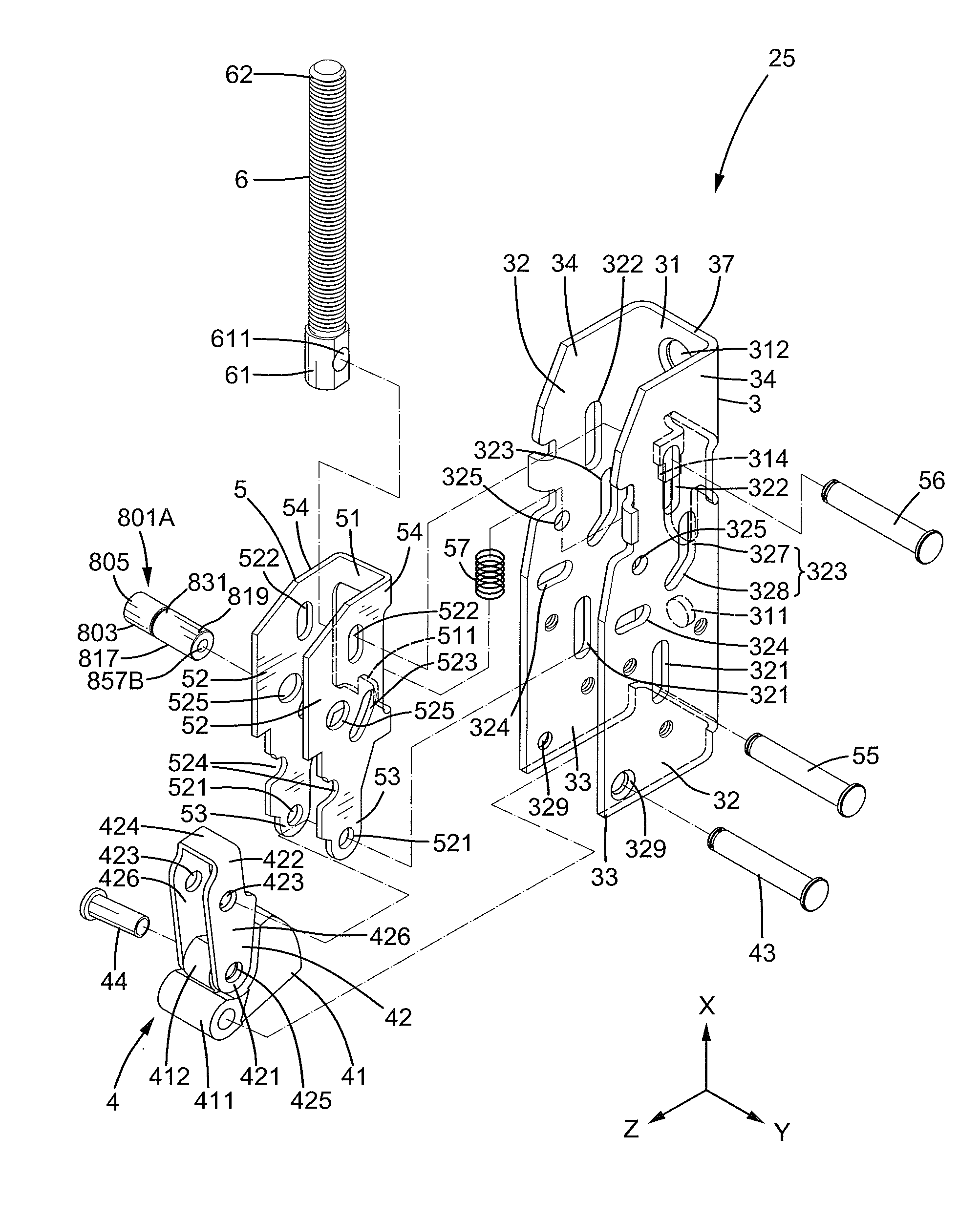
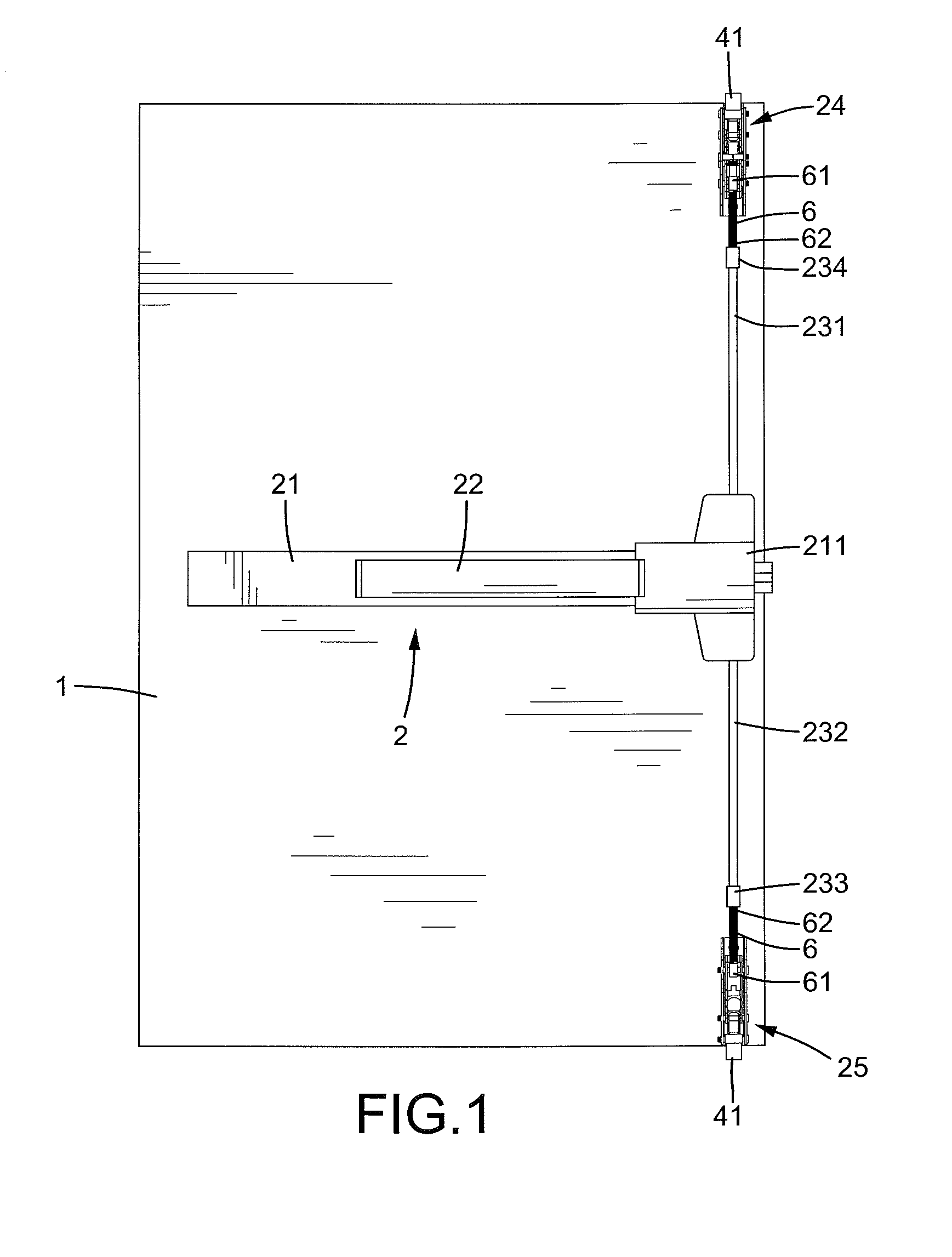
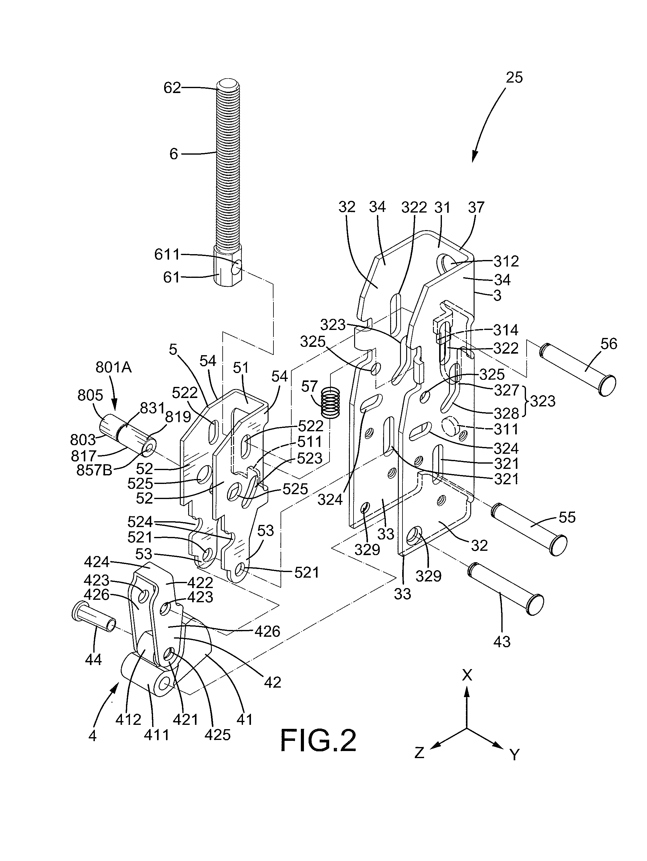
[0025]FIG. 1 shows a fireproof door lock 2 mounted to a fireproof door 1 in a panic exit or the like. In the form shown, door lock 2 includes a housing 21 is mounted to door 1, a touch bar 22 mounted outside housing 21 for manual operation, and a transmission mechanism (not shown) mounted in an end 211 of housing 21. Door lock 2 further includes a top latch 24 and an upper vertical rod 231 having a lower end coupled with the transmission mechanism and an upper end 234 coupled with top latch 24. Door lock 2 further includes a bottom latch 25 and a lower vertical rod 232 having an upper end coupled with the transmission mechanism and a lower end 233 coupled with bottom latch 25. When touch bar 22 is pressed, upper and lower vertical rods 231 and 232 are moved toward each other in a vertical direction to unlatch top and bottom latches 24 and 25. The transmission mechanism can be of any desired form as conventional including but not limited to of a commercially available type.

[0026]In t...


PUM


Abstract

A latch assembly includes a base having two sidewalls each having a positioning hole. A follower plate includes two sidewalls each having an engagement hole that is aligned with the positioning holes when the latch is in a latching position and that is not aligned with the positioning holes when the latch is in an unlatching position. Two sleeves are mounted between the sidewalls of the follower plate. An end of each sleeve is received in the engagement hole of one of the sidewalls of the follower plate. A stop having a low melting point is received in each sleeve to retain a safety pin in the sleeve. When the stops melt due to heat of a fire while the latch is in the latching position, the safety pins are moved by a spring into the positioning holes of the base to retain the latch in the latching position.

Description

BACKGROUND OF THE INVENTION[0001]The present invention relates to a latch assembly for a fireproof door lock and, more particularly, to a latch assembly with a safety device for a fireproof door lock for a door mounted in a passageway or panic exit, with top and bottom latches of the fireproof door lock retained in the latching positions during a fire to avoid expansion of the fire and smoke by avoiding opening of the door.[0002]Fireproof door locks are generally mounted to fireproof doors in passageways or panic exits and generally include horizontal type latches and vertical type latches. Vertical type latches include a top latch and a bottom latch. The fireproof lock door should be remained in the closed position during a fire to avoid expansion of the fire or smoke. However, the parts of the fireproof door lock may deform due to the high temperature of the fire, such that the door can not be retained in the closed position. Specifically, the latch bolts of the top and bottom lat...

Claims


Application Information

Patent Timeline
Patent Type & Authority Applications(United States)
IPC IPC(8): E05B65/10
CPCE05B65/104E05B65/1006Y10T292/0908Y10T292/0909Y10T292/1043
Inventor TIEN, HUNG-JEN
Owner I TEK METAL MFG
Why Eureka
Try Eureka