

Hair Removal Cartridge with Elongated Recess Region
- Summary
- Abstract
- Description
- Claims
- Application Information
AI Technical Summary
Benefits of technology
Problems solved by technology
Method used
Image

Examples
Embodiment Construction
[0026]The present disclosure is not limited to wet shaving razors, or even razors in general. It is understood that certain aspects of the present disclosure may also be used for dry electric shaving razors that have one or more rotating or reciprocating blades or other personal care appliances (e.g., toothbrushes, depilatory applicators, epilators, or other beauty applicators). Furthermore, it is understood that certain aspects of the present disclosure may be used independently of applying a liquid (e.g., a cartridge and a dispensing unit 150 may be used independently).
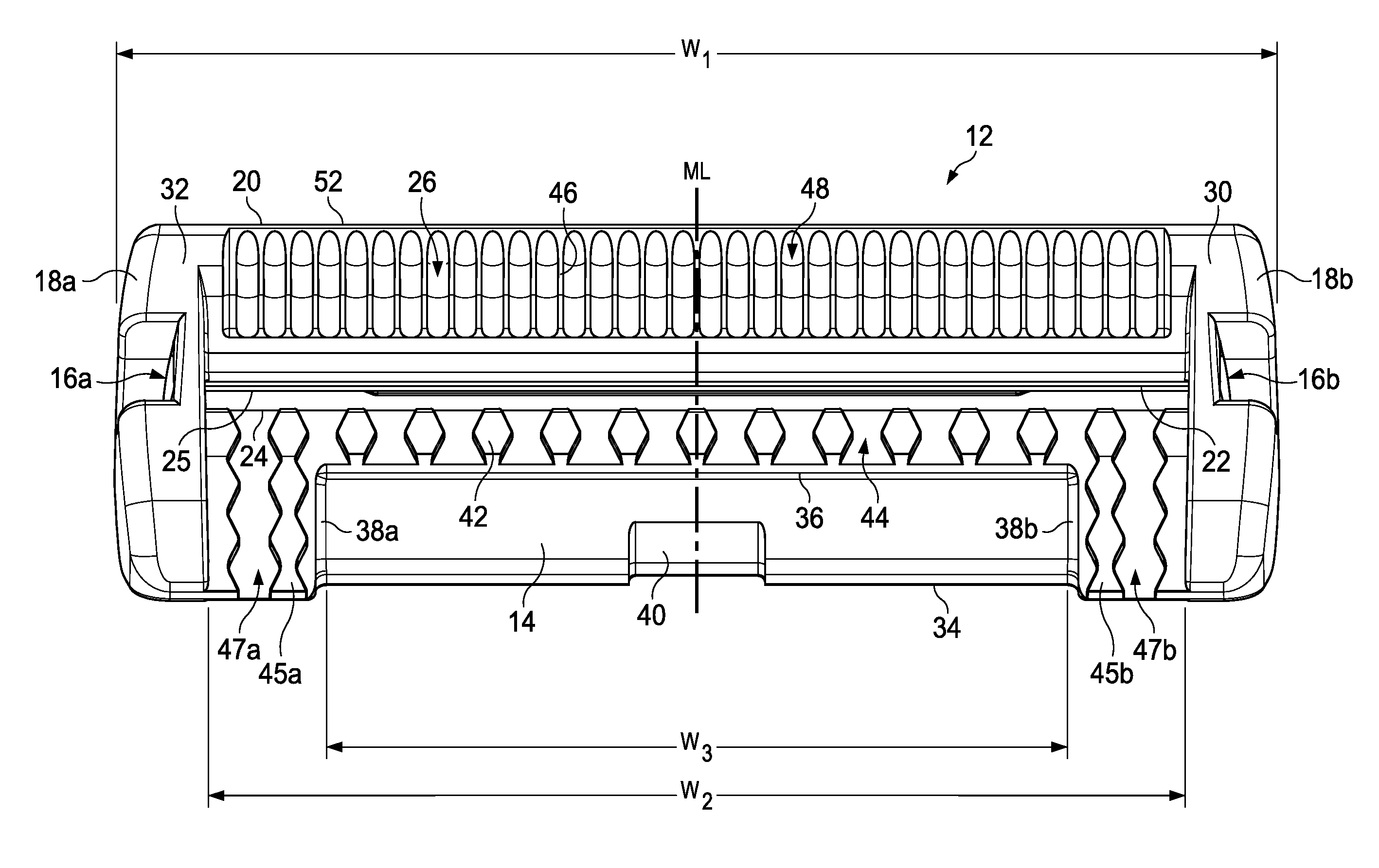
[0027]The present disclosure is not limited to shaving cartridges in which the blades are rigidly mounted in a fixed position relative to a guard and / or a cap. If the blades are capable of movement then the geometric parameters stipulated herein are those which apply when the blades are in their normal rest positions. Each of the illustrated safety razor blade units are intended to be mounted on a razor handle. The ...
PUM
 Abstract
Description
Claims
Application Information