Remote Control Floating Fishing Light

a floating light and remote control technology, applied in the field of floating lights, can solve the problems of limited range of hand-held or mounted fishing lights, inability to effectively illuminate obstacles at normal casting distance, etc., and achieve the effects of smooth low profile, safe illumination of obstacles, and avoiding wind resistan

Inactive Publication Date: 2013-05-02
TUCKER DANNY R +1
View PDF4 Cites 13 Cited by
  • Summary
  • Abstract
  • Description
  • Claims
  • Application Information

AI Technical Summary

Benefits of technology

[0008]The present invention is directed to a floating light to aid a nighttime fisherman. The light is maneuverable by remote control and is directional. The floating light comprises a light mounted onto a floating vessel which is propellable and maneuverable by means such as a propeller driven by an electric motor and a remote controlled rudder. The floating light may be referred to herein as a “boat.” The light source may any of various types, such as LED or fluorescent. The light desirably operates on battery power for several hours at a time. The light is directed at the surface of the water or just above the surface so that a fisherman is able to illuminate a desired area when fishing at night. The light thus allows the fisherman to safely illuminate obstacles, such as rocks, logs, vegetation, stumps and the like. The vessel desirably operates by radio frequency (RF) remote control at “casting distance,” i.e., 30-40 feet from the fisherman's boat. The vessel is preferably provided with a smooth low profile to avoid wind resistance and allow for greater ease of maneuverability.

Problems solved by technology

However, lights that are hand held or mounted to the fishing boat are limited in their range and may not be able to effectively illuminate obstacles at normal casting distance.

Method used


Image

  • Remote Control Floating Fishing Light
  • Remote Control Floating Fishing Light
  • Remote Control Floating Fishing Light

Examples


Embodiment Construction

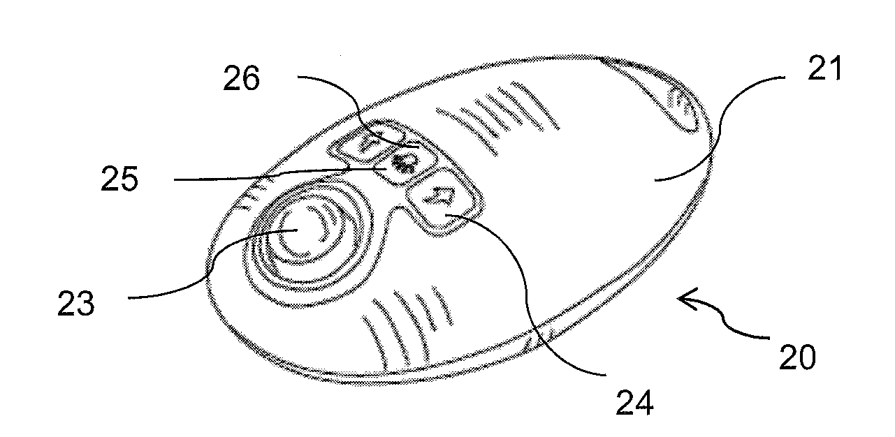
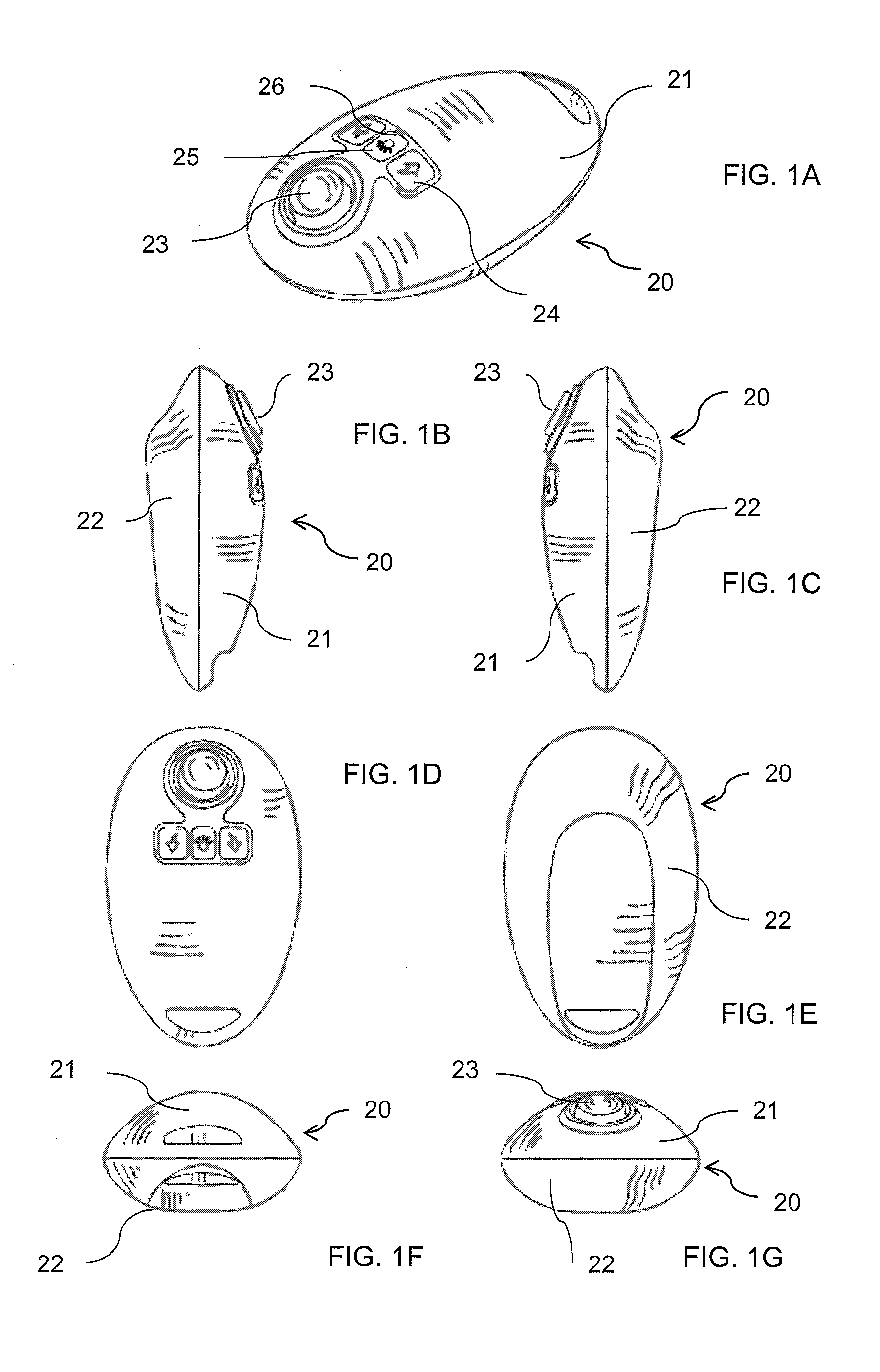
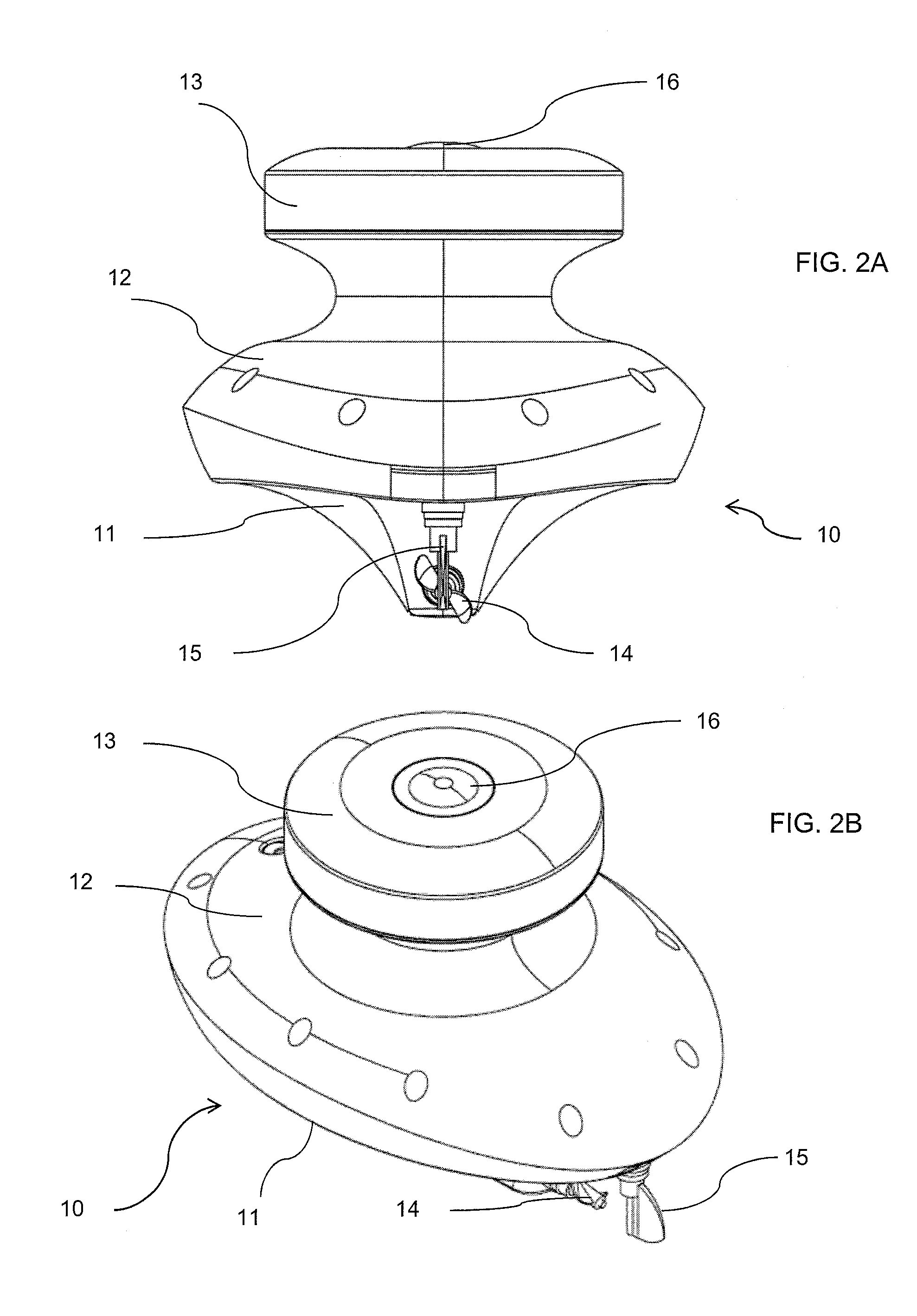
[0021]With reference to FIGS. 1A-9I, the preferred embodiments of the present invention may be described. The present invention is directed to a floating light 10 to aid a nighttime fisherman. The light is 10 maneuverable by remote control and the light is directional. The floating light 10 comprises a directional light 13 mounted onto a floating vessel which is propellable and maneuverable by means such as a propeller driven by an electric motor and a remote controlled rudder. The electric motor may be either a brushed or brushless type. A motor providing a no load speed of 17,000 rpm and a load speed of 10,000 rpm when used with a 7.4 volt power supply would be suitable. The light source may be any of various types, such as LED or fluorescent. The floating light 10 desirably operates on battery power for several hours at a time. The floating light 10 is directed at the surface of the water or just above the surface so that a fisherman is able to illuminate a desired area when fish...


PUM


Abstract

A floating light (10) to aid a night time fisherman. The floating light (10) is maneuverable by remote control (20). The floating light (10) includes a battery operated directional light (13) mounted onto a floating vessel. The directional light (13) is directed at the surface of the water or just above the surface so that a fisherman is able to illuminate a desired area when fishing at night to safely illuminate obstacles. The floating light (10) desirably operates at “casting distance” and has a smooth low profile. The floating light (10) may include a motor driven propeller (14) and rudder (15) operably connected to a radio remote control receiver (45). A radio remote control transmitter (27) operable by the fisherman transmits signals to the receiver (45) on the floating light (10) to direct the motion of the floating light (10).

Description

CROSS-REFERENCE TO RELATED APPLICATIONS[0001]This application claims the benefit of U.S. Provisional Patent Application No. 61 / 628,255 filed Oct. 27, 2011, which is incorporated herein by reference in its entirety.STATEMENT REGARDING FEDERALLY SPONSORED RESEARCH OR DEVELOPMENT[0002]Not applicable.BACKGROUND OF THE INVENTION[0003]1. Field of the Invention[0004]The present invention relates to a floating light to aid a nighttime fisherman, and in particular, to such a light that is maneuverable by remote control and which is directional.[0005]2. Brief Description of the Related Art[0006]When fishing at night, a fisherman must be aware of obstacles that are either safety hazards or that might interfere with casting and retrieving the fishing line. These obstacles include rocks, logs, vegetation, stumps and the like. These obstacles can be seen and avoided by the use of suitable illumination. However, lights that are hand held or mounted to the fishing boat are limited in their range an...

Claims


Application Information

Patent Timeline
Patent Type & Authority Applications(United States)
IPC IPC(8): F21L4/00
CPCA63H30/04F21S9/02F21Y2103/00F21V23/0435F21Y2101/02F21V15/01F21Y2115/10
Inventor TUCKER, DANNY R.OSTRANDER, CHRISTOPHER J.SCHWEPPE, DERICK R.VAN HORN, SCOTT B.
Owner TUCKER DANNY R
Why Eureka
Try Eureka