Cylindrical linear motor with laminated stator

a stator and cylindrical technology, applied in the direction of dynamo-electric machines, electrical apparatus, magnetic circuits, etc., can solve the problems of time delay in the buildup of force, no cylindrical linear motors have been used in the prior art for highly dynamic driving functions, and the iron of the stator is due to time delay, etc., to achieve the effect of safe housing

Inactive Publication Date: 2013-05-23
SIEMENS AG
View PDF6 Cites 5 Cited by
  • Summary
  • Abstract
  • Description
  • Claims
  • Application Information

AI Technical Summary

Benefits of technology

[0009]What is advantageously achieved by means of the lamination of the stator core is that the eddy currents in the stator core or stator iron are reduced and as a result the losses are also minimized. Furthermore this makes a field displacement all the less likely to occur, with the result that a faster force buildup is possible.
[0014]According to another advantageous feature of the present invention, the stator comb element can have an axially running channel in which a connecting circuit of the annular coils is arranged. This enables the comb element to be used also for accommodating and fixing switching elements for the circuit or interconnection of the windings.
[0015]According to another advantageous feature of the present invention, the stator comb element can have an electrically insulating plastic part, an electrically insulated cast part or an electrically insulated sintered part. Materials of this kind can ensure that the connecting circuit of the windings can be safely accommodated at the stator.
[0016]According to another advantageous feature of the present invention, the individual laminations of the stator core can be fixed in position at each axial end of the stator by fixing rings, respectively. In this way the individual laminations are retained radially fixed or pre-fixed at the stator core.
[0017]According to another advantageous feature of the present invention, the stator core can be enclosed by a housing or a cooling jacket. In this way it is possible to protect the stator or cool it as appropriate.
[0018]According to another advantageous feature of the present invention, the stator core can be sealed with a resin. As a result, any gaps between the individual laminations, which are in fact arranged in a star shape, can be closed, thereby stabilizing the stator core.

Problems solved by technology

In such applications, losses result in the stator iron due to eddy currents.
In addition the eddy currents cause a field displacement which leads to a time delay in the force buildup.
No cylindrical linear motors have been used in the prior art for highly dynamic driving functions.

Method used


Image

  • Cylindrical linear motor with laminated stator
  • Cylindrical linear motor with laminated stator
  • Cylindrical linear motor with laminated stator

Examples


Embodiment Construction

[0027]Throughout all the figures, same or corresponding elements may generally be indicated by same reference numerals. These depicted embodiments are to be understood as illustrative of the invention and not as limiting in any way. It should also be understood that the figures are not necessarily to scale and that the embodiments are sometimes illustrated by graphic symbols, phantom lines, diagrammatic representations and fragmentary views. In certain instances, details which are not necessary for an understanding of the present invention or which render other details difficult to perceive may have been omitted.

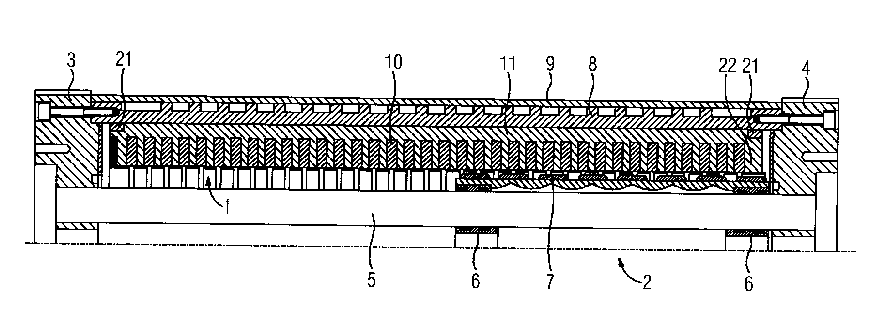
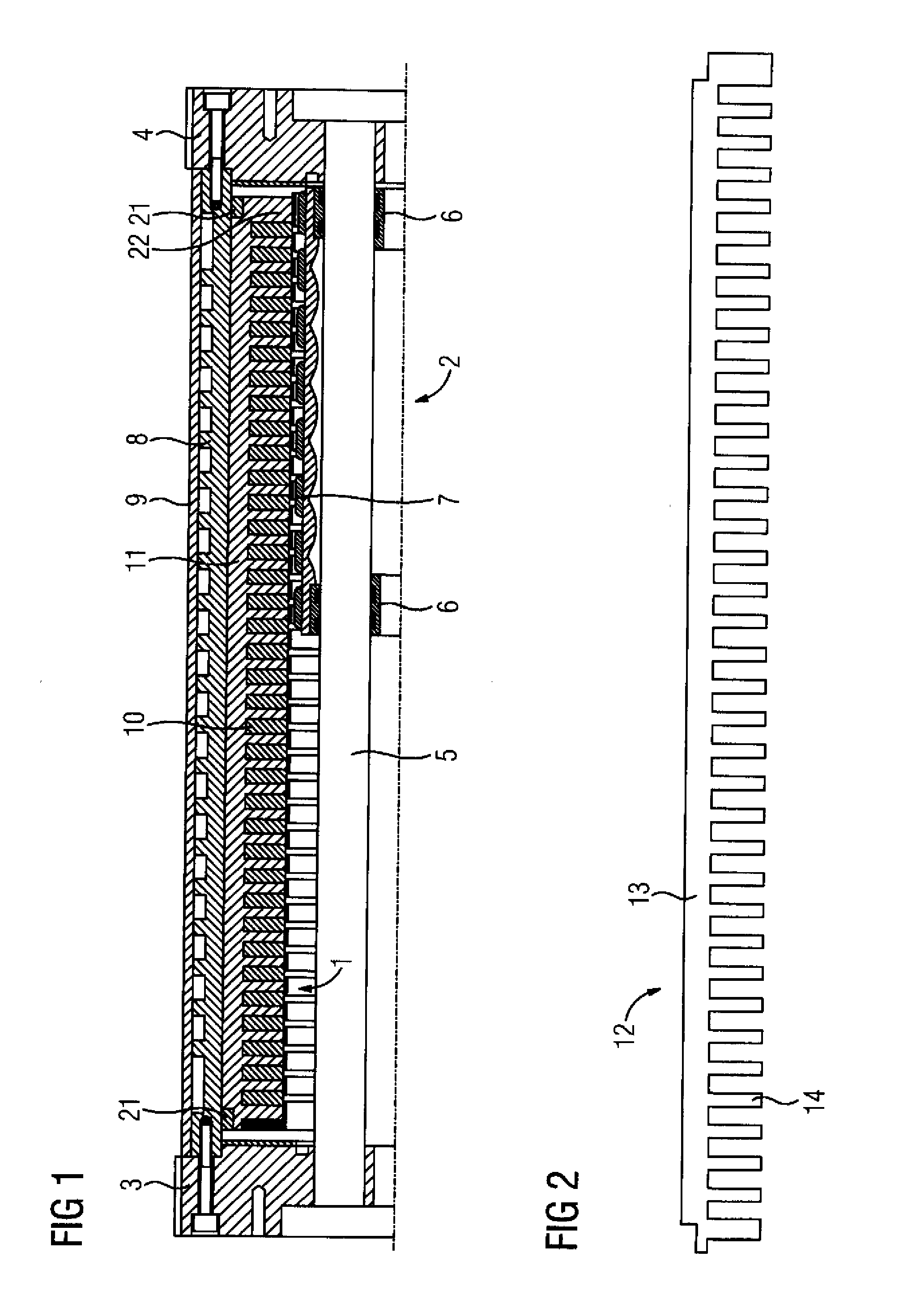
[0028]Turning now to the drawing, and in particular to FIG. 1, there is shown a cross-section through a part of a cylindrical linear motor according to the present invention, having a stator 1 which is likewise embodied in a cylinder shape and is presented in a perspective view in FIG. 4. A likewise cylindrical rotor 2 is coaxially located in the cylindrical stator 1. End sh...


PUM


Abstract

A cylindrical linear motor includes a cylindrical rotor, and a cylindrical stator arranged in coaxial relationship to the rotor. The stator has a plurality of annular coils which are arranged in coaxial relationship, and a ferromagnetic stator core which includes a plurality of individual laminations which are aligned radially or arranged in a star shape. This reduces a field displacement caused by eddy currents, as a result of which ultimately a time delay in the force buildup is also reduced.

Description

CROSS-REFERENCES TO RELATED APPLICATIONS[0001]This application claims the priority of European Patent Application, Serial No. EP 11166064, filed May 13, 2011, pursuant to 35 U.S.C. 119(a)-(d), the content of which is incorporated herein by reference in its entirety as if fully set forth herein.BACKGROUND OF THE INVENTION[0002]The present invention relates to a cylindrical linear motor with laminated stator.[0003]The following discussion of related art is provided to assist the reader in understanding the advantages of the invention, and is not to be construed as an admission that this related art is prior art to this invention.[0004]Linear motors can be implemented in a cylindrical design. Linear motors of said type are typically employed for initiating linear movements whose frequency lies in the single-digit hertz range. In this case the stator core is embodied as a hollow cylinder and on its inside has slots running in the circumferential direction. Annular coils are inserted int...

Claims


Application Information

Patent Timeline
Patent Type & Authority Applications(United States)
IPC IPC(8): H02K41/03
CPCH02K1/145H02K41/031H02K41/03
Inventor FICK, MICHAELSTABLEIN, ARMINVOLLMER, ROLF
Owner SIEMENS AG
Why Eureka
Try Eureka