
Vehicle body lower portion structure

a lower portion and vehicle body technology, applied in the direction of roofs, transportation and packaging, vehicle arrangements, etc., can solve the problem of difficult to efficiently transmit the collision load to the side opposite to the collision, and achieve the effect of efficient absorption and dispersion of load

Active Publication Date: 2013-06-20
TOYOTA JIDOSHA KK
View PDF1 Cites 7 Cited by
  • Summary
  • Abstract
  • Description
  • Claims
  • Application Information

AI Technical Summary

Benefits of technology

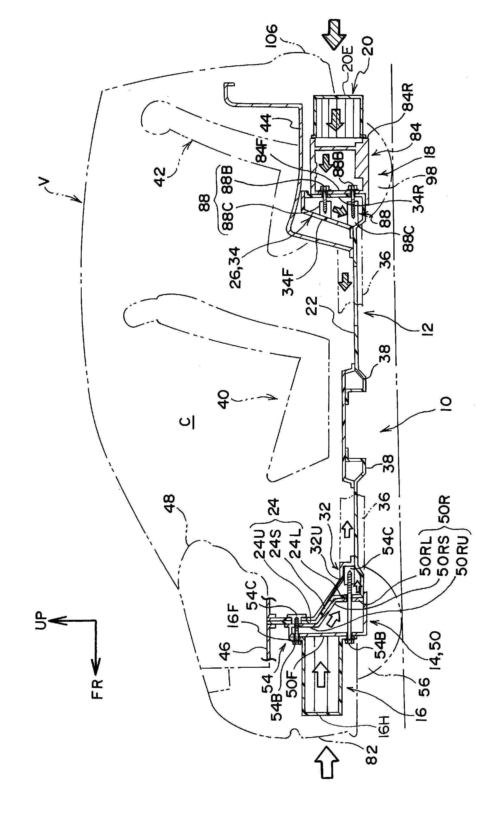
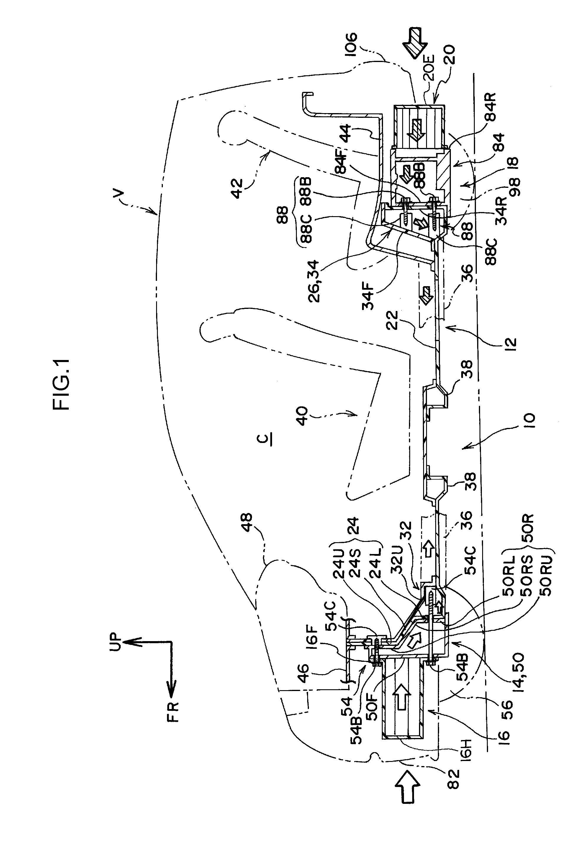
The vehicle body lower portion structure described in this patent can efficiently absorb and disperse the impact from a front or rear collision, including an offset or oblique collision. It then transmits the load to the underbody of the vehicle.

Problems solved by technology

In a structure in which a load of a front collision is received at a pair of left and right front side members, it is difficult to efficiently transmit the collision load to a side opposite to the collision, at the time of an offset collision or an oblique collision or the like for example.

Method used


Image

  • Vehicle body lower portion structure
  • Vehicle body lower portion structure
  • Vehicle body lower portion structure

Examples


modified examples

[0099]Note that the above-described embodiment illustrates an example in which the front EA member 16 side at the suspension member 50 is a wide, flat surface, but the present invention is not limited to this. For example, there can be made to be a modified example such as shown in FIG. 9 or FIG. 10.

[0100]The suspension member 50, that relates to a first modified example and is shown in FIG. 9, has, instead of the front wall 50F that is rectangular in front view, a frame-shaped wall 108 that is formed in a rectangular frame shape in front view. The flange 16F of the front EA member 16 contacts the frame-shaped wall 108 over the entire periphery.

[0101]In a second modified example shown in FIG. 10, instead of the suspension member 50, there is provided a suspension member 110 that is formed in a rectangular frame shape overall. Note that, in FIG. 10, illustration of the front suspension unit 52 is omitted.

[0102]At the suspension member 110, an upper cross portion 110U, a lower cross p...


PUM


Abstract

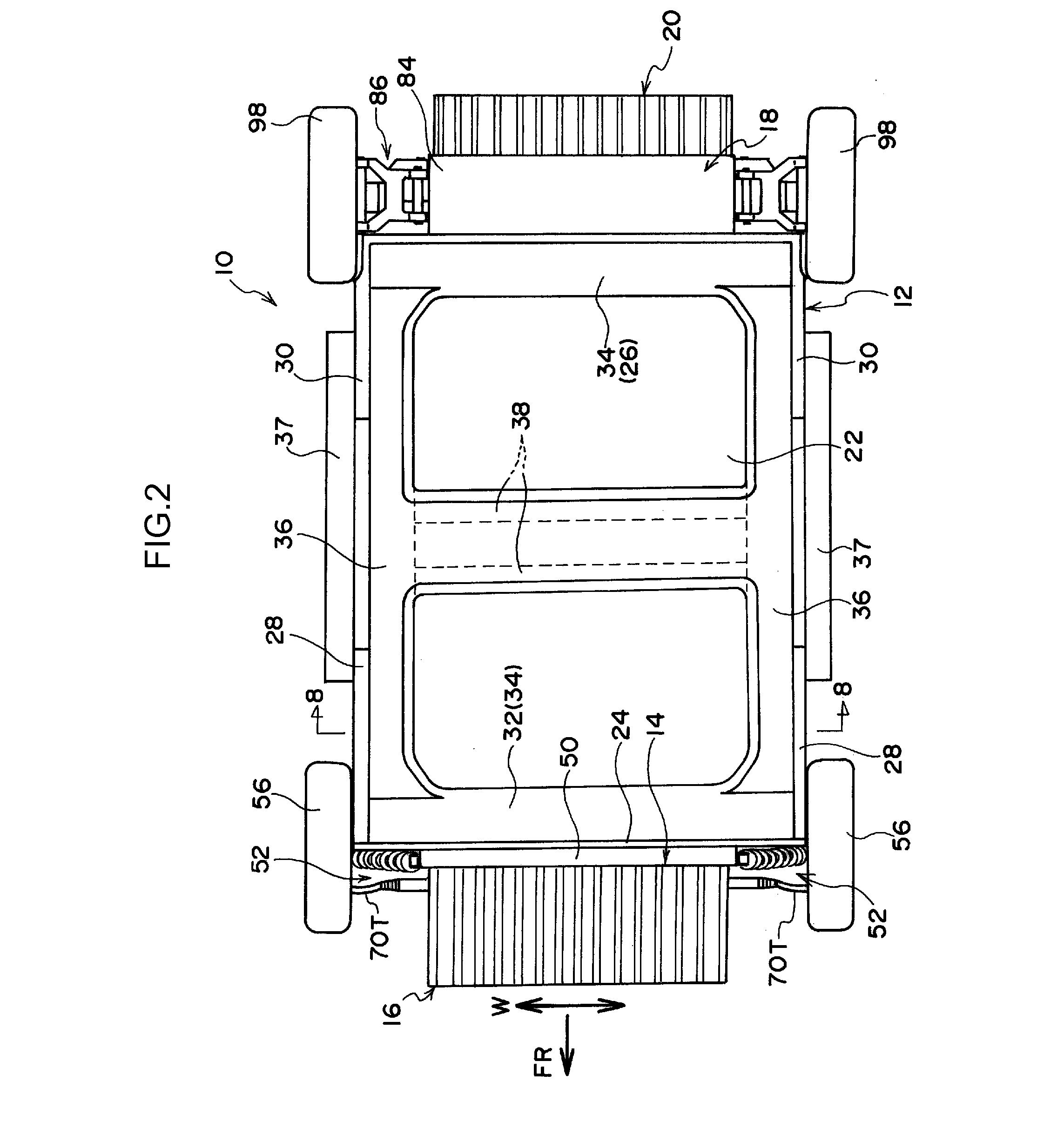
To obtain a vehicle body lower portion structure that can efficiently absorb and disperse load of a front or rear collision including an offset collision or an oblique collision, and transmit the load to an underbody. A vehicle body lower portion structure has an underbody at which a dash lower portion and a lower back portion are provided to stand from both ends in a vehicle front-rear direction at a floor portion, a suspension member the length direction thereof is along a vehicle transverse direction and is joined to the underbody in a state of planarly-contacting a front surface of the dash lower portion, and a front EA member a length direction thereof is along the vehicle transverse direction and is joined to a front wall of the suspension member.

Description

TECHNICAL FIELD[0001]The present invention relates to a vehicle body lower portion structure that has an underbody at which standing walls are provided so as to stand from both ends, in the vehicle longitudinal direction, at a floor portion.BACKGROUND ART[0002]There is known a lower portion structure of a vehicle front body portion that disperses a load of a front collision, that is inputted to a front side member, to a tunnel member via an inner torque box, and disperses the load to a rocker rail via an outer torque box (see, for example, Japanese Patent Application Laid-Open No. 2005-162144). Further, a vehicle front portion structure is known in which a hollow structural body, whose cross-sectional shape in plan view is lattice-shaped, is disposed for impact absorption between left and right front side members such that dependence on front side members regarding the impact absorption performance at the time of a front collision is lowered (see, for example, Japanese Patent Applic...

Claims


Application Information

Patent Timeline
Patent Type & Authority Applications(United States)
IPC IPC(8): B62D21/15
CPCB62D21/152B62D21/15B62D25/20B62D25/14
Inventor SOTOYAMA, YOSHITAKAIKEDA, KOKIINAMORI, SHIGERUSEKI, KAZUHIROIWAMOTO, HIROAKIONO, MASAHIROMAEDA, SHO
Owner TOYOTA JIDOSHA KK
Learn More