
Vehicle body lower portion structure

a lower portion and vehicle body technology, applied in the direction of roofs, transportation and packaging, vehicle arrangements, etc., can solve the problem of difficult to efficiently transmit the collision load to the side opposite to the collision, and achieve the effect of efficient absorption and dispersion of load

Active Publication Date: 2014-01-28
TOYOTA JIDOSHA KK
View PDF25 Cites 11 Cited by
  • Summary
  • Abstract
  • Description
  • Claims
  • Application Information

AI Technical Summary

Benefits of technology

The vehicle body lower portion structure described in the patent is effective at absorbing and dispersing the impact of collisions, including front or rear collisions, and transmitting the impact to the underbody of the vehicle. This results in a safer and more effective absorption of collisions, improving the vehicle's overall performance and safety.

Problems solved by technology

In a structure in which a load of a front collision is received at a pair of left and right front side members, it is difficult to efficiently transmit the collision load to a side opposite to the collision, at the time of an offset collision or an oblique collision or the like for example.

Method used


Image

  • Vehicle body lower portion structure
  • Vehicle body lower portion structure
  • Vehicle body lower portion structure

Examples


Embodiment Construction

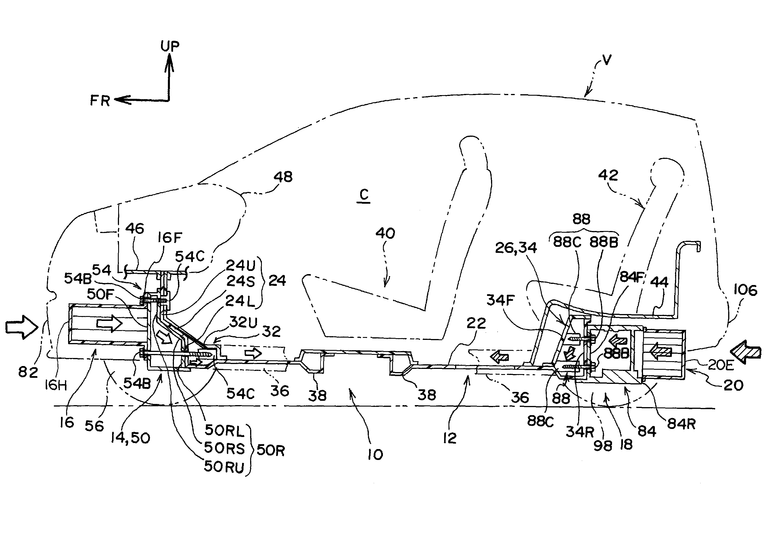
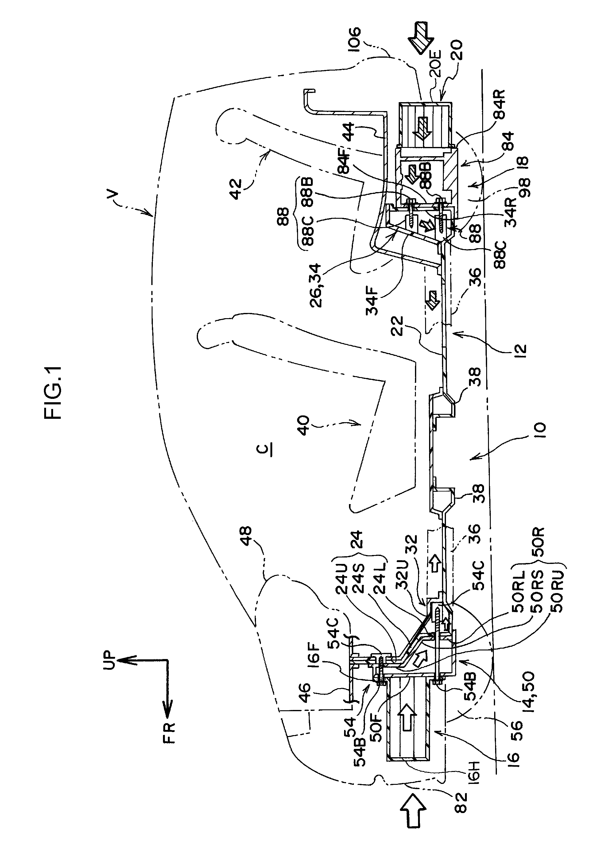
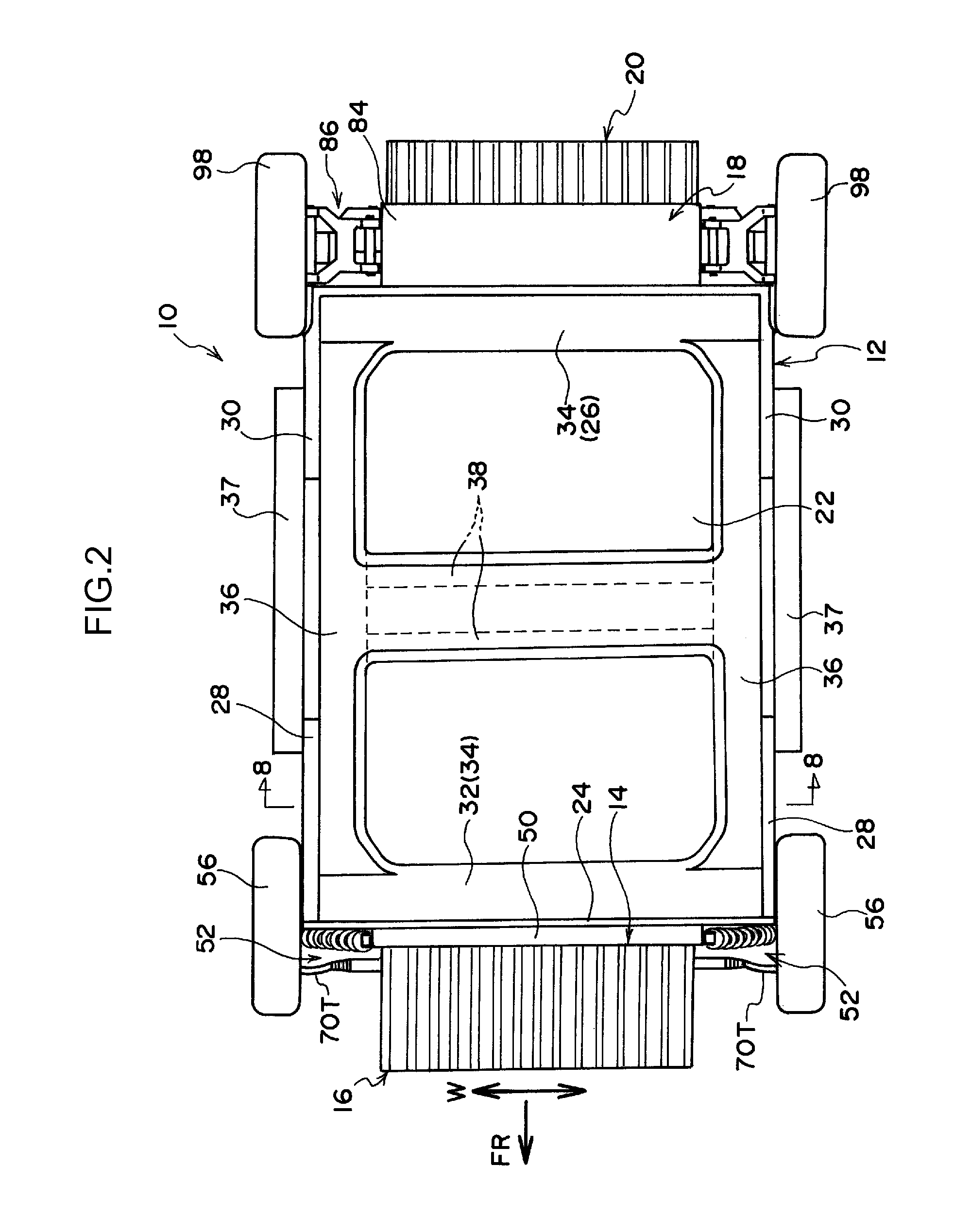
[0029]A vehicle body lower portion structure 10 relating to an embodiment of the present invention is described on the basis of FIG. 1 through FIG. 5. Note that arrow FR shown appropriately in the drawings indicates the forward direction in the vehicle front-rear direction, arrow UP indicates the upward direction in the vehicle up-down direction, and arrow W indicates the vehicle transverse direction, respectively. In the following description, unless specially noted, when front / rear and up / down are used, they indicate front / rear direction in the vehicle front-rear direction and up / down direction in the vehicle up-down direction.

[0030]An automobile V to which the vehicle body lower portion structure 10 is applied is shown in FIG. 1 in a side sectional view. Further, the vehicle body lower portion structure 10 is shown in FIG. 2 in a plan view. An exploded perspective view of the vehicle body lower portion structure 10 is shown in FIG. 3. As shown in these drawings, the vehicle body ...


PUM


Abstract

To obtain a vehicle body lower portion structure that can efficiently absorb and disperse load of a front or rear collision including an offset collision or an oblique collision, and transmit the load to an underbody. A vehicle body lower portion structure has an underbody at which a dash lower portion and a lower back portion are provided to stand from both ends in a vehicle front-rear direction at a floor portion, a suspension member the length direction thereof is along a vehicle transverse direction and is joined to the underbody in a state of planarly-contacting a front surface of the dash lower portion, and a front EA member a length direction thereof is along the vehicle transverse direction and is joined to a front wall of the suspension member.

Description

CROSS-REFERENCE TO RELATED APPLICATIONS[0001]This application is a United States National Stage Patent Application filed under 35 U.S.C. §371, based on International Application Serial No. PCT / JP2010 / 064750, which was filed on Aug. 30, 2010, the entire contents of which is expressly incorporated herein by reference.TECHNICAL FIELD[0002]The present invention relates to a vehicle body lower portion structure that has an underbody at which standing walls are provided so as to stand from both ends, in the vehicle longitudinal direction, at a floor portion.BACKGROUND ART[0003]There is known a lower portion structure of a vehicle front body portion that disperses a load of a front collision, that is inputted to a front side member, to a tunnel member via an inner torque box, and disperses the load to a rocker rail via an outer torque box (see, for example, Japanese Patent Application Laid-Open No. 2005-162144). Further, a vehicle front portion structure is known in which a hollow structur...

Claims


Application Information

Patent Timeline
Patent Type & Authority Patents(United States)
IPC IPC(8): B62D25/20
CPCB62D25/14B62D25/20B62D21/152B62D21/15
Inventor SOTOYAMA, YOSHITAKAIKEDA, KOKIINAMORI, SHIGERUSEKI, KAZUHIROIWAMOTO, HIROAKIONO, MASAHIROMAEDA, SHO
Owner TOYOTA JIDOSHA KK
Learn More