Reducing agent aqueous solution mixing device and exhaust gas post-treatment device

a technology of reducing agent and aqueous solution, which is applied in the direction of machines/engines, lighting and heating apparatus, separation processes, etc., can solve the problems of large amount of heat required to evaporate the droplets attached to the inner pipe, the inability to supply ammonia to the reducing catalyst unit, and the inability to easily decompose urea aqueous solution, etc., to achieve the effect of inhibiting the deterioration of fuel consumption and reducing flow path resistan

Active Publication Date: 2013-06-27
KOMATSU LTD
View PDF3 Cites 39 Cited by
  • Summary
  • Abstract
  • Description
  • Claims
  • Application Information

AI Technical Summary

Benefits of technology

[0010]It is an object of the present invention to inhibit a reducing agent aqueous solution such as a urea aqueous solution added to exhaust gas from attaching to the inner wall of an exhaust pipe, and simultaneously, reduce the flow path resistance within the exhaust pipe, in a device tier mixing the reducing agent aqueous solution such as a urea aqueous solution with the exhaust gas.
[0037]According to the present aspect as described above, the reducing agent aqueous solution added to the exhaust gas can be inhibited from attaching to the inner wall of the exhaust pipe in the reducing agent aqueous solution mixing device. In addition, the flow path resistance within the exhaust pipe can be reduced, and deterioration in fuel consumption can be inhibited by inhibiting the back pressure of the engine.

Problems solved by technology

When the distance is short, the urea aqueous solution injected within the exhaust pipe is not sufficiently mixed with the exhaust gas, while partially attaching as droplets to the inner wall of the exhaust pipe cooled by the external The urea aqueous solution, thus attached to the inner wall of the exhaust pipe, is not easily decomposed.
Therefore, there may be deficiency in ammonia to be supplied to the reducing catalyst unit, Further, the urea aqueous solution, changed into droplets on the inner wall of the exhaust pipe, may be crystallized and deposited on the inner wall.
Therefore, a large amount of heat is required to evaporate the droplets attached to the inner pipe.
A sufficient amount of heat may not be reliably obtained only by the exhaust gas passing around the outer peripheral part of the inner pipe.
Therefore, this results in deterioration in fuel consumption.

Method used


Image

  • Reducing agent aqueous solution mixing device and exhaust gas post-treatment device
  • Reducing agent aqueous solution mixing device and exhaust gas post-treatment device
  • Reducing agent aqueous solution mixing device and exhaust gas post-treatment device

Examples


Embodiment Construction

Overall Structure

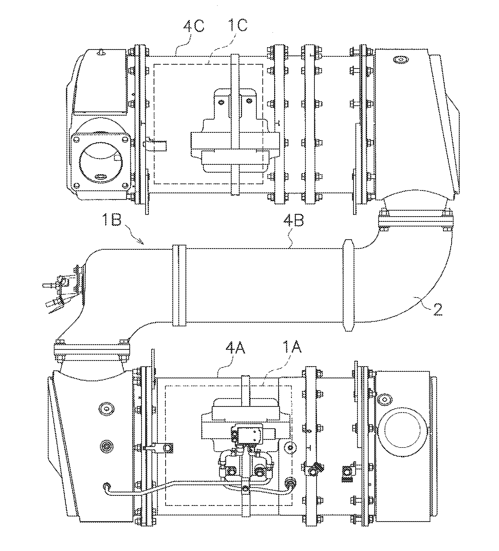
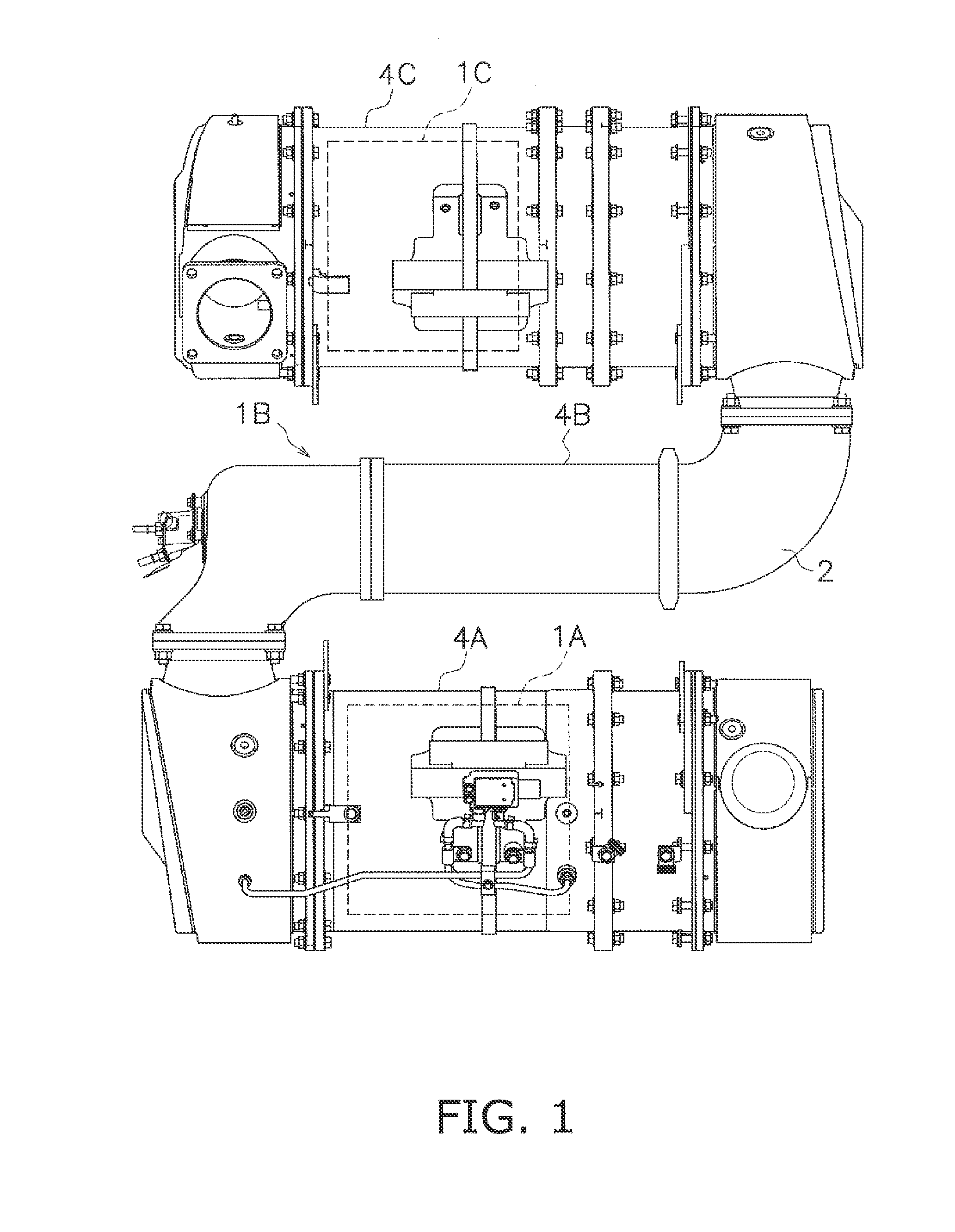
[0048]FIG. 1 is a structural diagram of an exhaust gas post-treatment device 1 according to an exemplary embodiment of the present invention. The exhaust gas post-treatment device 1 includes a diesel particulate filter (hereinafter referred to as “DPF”) 1A, a urea aqueous solution mixing device 1B and a nitrogen oxide reducing catalyst unit (hereinafter referred to as “SCR”) 1C, which are sequentially disposed from an exhaust upstream side (hereinafter simply referred to as “an upstream side”). Each of the devices is disposed in an intermediate portion of an exhaust pipe through which exhaust gas, discharged from a diesel engine (not illustrated in the figure) through an exhaust manifold, flows.

[0049]The DPF 1A serves to trap particulate substance in the exhaust gas and is accommodated within a case 4A.

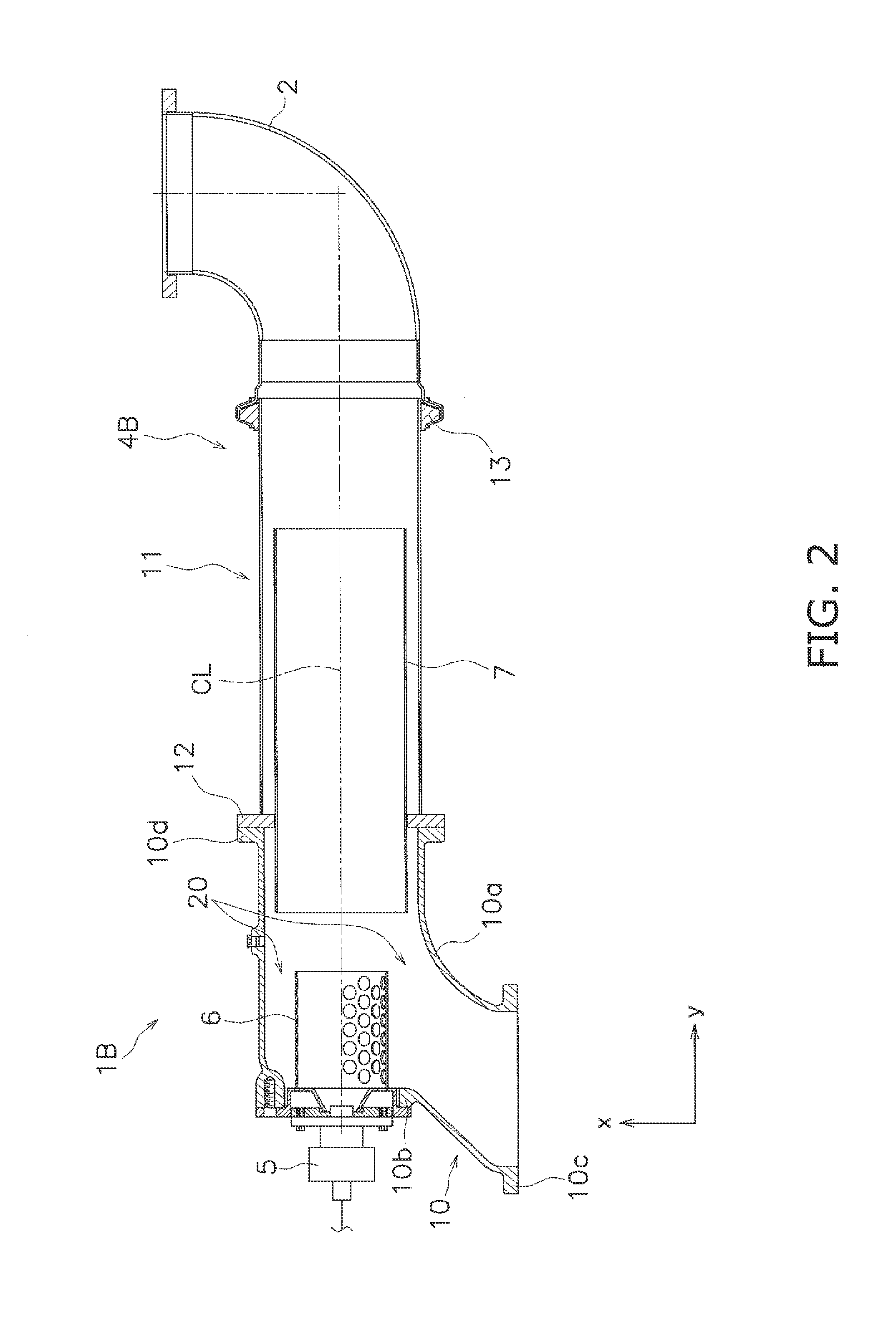
[0050]The urea aqueous solution mixing device 1B serves to add a urea aqueous solution as a reducing agent to the exhaust gas. The added urea aqueous solution is hydr...


PUM

PropertyMeasurementUnit
injection angleaaaaaaaaaa
angleaaaaaaaaaa
inner diameteraaaaaaaaaa

Abstract

A reducing agent aqueous solution mixing device includes an exhaust pipe, an injector, a mixing pipe, an inner pipe and a flow section. The exhaust pipe includes an elbow part and a linear part. The injector is disposed in the elbow part and injects a reducing agent aqueous solution. The mixing pipe is disposed to enclose a surrounding of the reducing agent aqueous solution injected from the injector, and includes an outlet portion formed spaced apart from an inner wall of the exhaust pipe, and a plurality of openings formed on the outer peripheral surface thereof. The inner pipe is disposed in the linear part and allows the exhaust gas to flow through the inside and the outer periphery thereof. The flow section is formed between the outlet portion of the mixing the inner wall of the exhaust pipe and directs the exhaust gas to the inner pipe.

Description

CROSS-REFERENCE TO RELATED APPLICATIONS[0001]This application claims priority to Japanese Patent Application No. 2011-285449 filed on Dec. 27, 2011, the disclosure of which is hereby incorporated herein by reference in its entirety.TECHNICAL FIELD[0002]The present invention relates to a reducing agent aqueous solution mixing device, particularly to, a reducing agent aqueous solution mixing device for adding a reducing agent aqueous solution to exhaust gas, which is disposed between a filter for trapping particulate substance in the exhaust gas and a reducing catalyst unit for reducing and purifying nitrogen oxide in the exhaust gas while being disposed in parallel to the filler. Further, the present invention relates to an exhaust gas post-treatment device including the aforementioned reducing agent aqueous solution mixing device.BACKGROUND ART[0003]The exhaust gas of engines contains nitrogen oxide (NOx). An exhaust gas post-treatment device is disposed at an intermediate position ...

Claims


Application Information

Patent Timeline
Patent Type & Authority Applications(United States)
IPC IPC(8): B01D53/90
CPCB01D53/9431Y02T10/24B01D53/90F01N3/2066F01N3/2892F01N13/02F01N3/021F01N2240/20F01N2250/02F01N2470/18F01N2470/24F01N2610/02F01N2610/1453B01F5/0451B01F5/0659B01F3/04049B01D2251/2067Y02T10/12B01F23/2132B01F2025/931B01F25/3131B01F25/435
Inventor IIJIMA, TADASHIKIZAWA, HIROFUMIITOU, BOKUTSUJIMURA, SHINJIKATOU, TAKASHIORITA, TETSUONAMIMATSU, KANJIHARA, ISSEITOMIOKA, HIROYUKI
Owner KOMATSU LTD
Why Eureka
Try Eureka