Photocatalyst deodorization device

A photocatalyst and photocatalytic technology, applied in deodorization, physical/chemical process catalysts, household refrigeration devices, etc., can solve problems such as corrosion, reduced illumination, and inability to commercialize, reduce flow path resistance, and reduce pressure loss. , the effect of long life

Active Publication Date: 2015-02-25
TOSHIBA LIGHTING & TECH CORP
View PDF5 Cites 2 Cited by
  • Summary
  • Abstract
  • Description
  • Claims
  • Application Information

AI Technical Summary

Problems solved by technology

[0015] In the case where ammonia is decomposed assuming the above-mentioned short wavelength (near ultraviolet region or UV light), not only the permeability of ammonia into the sealing resin (such as epoxy resin or silicone resin) is extremely high, but also The deterioration of the sealing resin due to the wavelength, or the direct corrosion of the LED chip (LED die) or the LED chip and the gold base electrode due to the penetration of the sealing resin, leads to a decrease in the illuminance of the LED, and there is a problem that it cannot be commercialized

Method used


Image

  • Photocatalyst deodorization device
  • Photocatalyst deodorization device
  • Photocatalyst deodorization device

Examples


no. 1 Embodiment approach

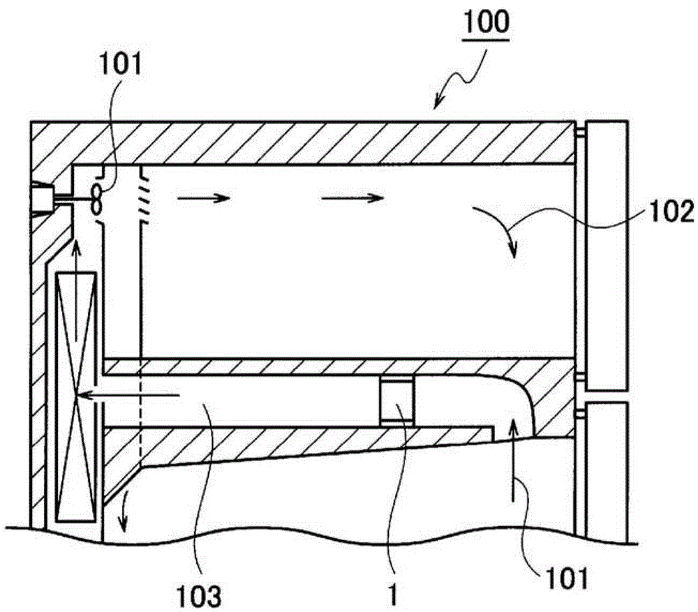
[0064] The photocatalyst deodorizing device 1 of an embodiment of the present invention is as figure 1 A device installed in the box of the refrigerator 100 for deodorization is shown. In the box of the refrigerator 100, the cooling fan 101 is used to circulate the cold air 102 in the box at a low wind speed, for example, a wind speed of 0.2 m / sec to 3 m / sec. The photocatalyst deodorizing device 1 of the present embodiment is installed in the cold air passage 103 for use in order to deodorize the air in the box without obstructing the flow of air at such a low wind speed.

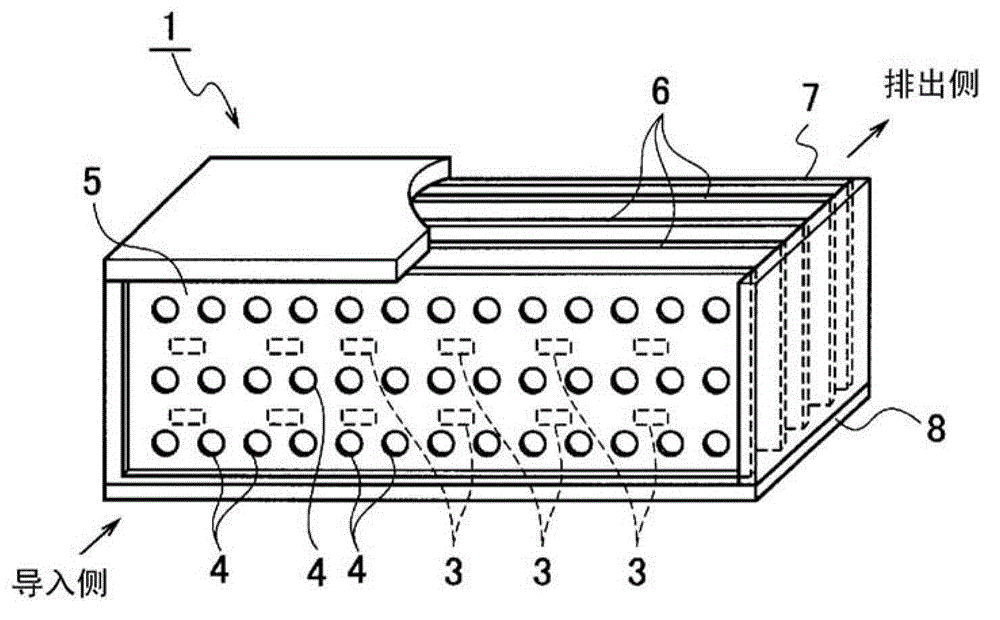
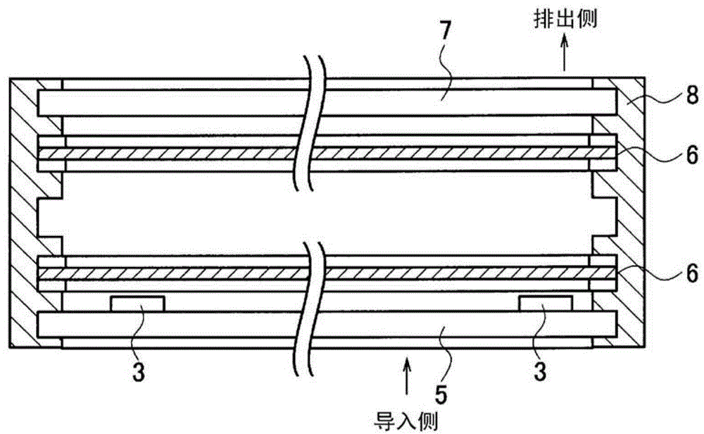
[0065] Such as Figure 2 ~ Figure 4 As shown, the photocatalyst deodorizing device 1 of the present embodiment is composed of LED3 for exciting the particles of the photocatalyst carried; an LED mounting substrate 5 provided with a plurality of vent holes 4 and mounted with LED3; and arranged substantially parallel to it A plurality of photocatalytic sheets 6; an opposing substrate 7 provided with ventilation ...

no. 2 Embodiment approach

[0083] Next, the photocatalyst deodorizing device 1 of the second embodiment of the present invention will be described. The photocatalyst deodorizing device 1 of this embodiment is also like figure 1 What is shown is a device installed in the box of the refrigerator 100 for deodorization. In addition, the structure of this embodiment is the same as that of the first embodiment, such as Figure 2 ~ Figure 4 As shown, LED3 used to excite the particles of the supported photocatalyst; LED mounting substrate 5 provided with a plurality of vent holes 4 and mounted with LED3; a plurality of photocatalytic sheets 6 arranged substantially parallel to it; and The LED mounting substrate 5 is provided with a counter substrate 7 provided with vent holes 4 arranged substantially parallel to each other, and a housing 8 formed of a frame that maintains the positions of these plates and maintains a reinforced shape.

[0084] In the case of this embodiment, the wavelength of the LED3 mounted on t...

Embodiment 1

[0092] Using the photocatalyst deodorizing device 1 of the first embodiment, the area using the photocatalyst sheet is 50 cm 2 , 1g of titanium oxide (80% of anatase type, 20% of rutile type) is supported on the photocatalyst, and the intensity of light generated by LED3 using ultraviolet light is 2mW / cm 2 The photocatalyst deodorizing device 1 was tested in a refrigerator with an initial concentration of 5 ppm of acetaldehyde. Such as Picture 9 As shown in the graph, when compared with the deodorizing performance of the photocatalyst deodorizing device using the conventional example, it was confirmed that the acetaldehyde decomposition performance of the photocatalyst deodorizing device of Example 1 was about 10% higher.


PUM

PropertyMeasurementUnit
diameteraaaaaaaaaa
diameteraaaaaaaaaa
wavelengthaaaaaaaaaa

Abstract

Disclosed is a long-life photocatalyst deodorization device (1) which effectively excites photocatalysts over the entire surface of a photocatalyst sheet and is capable of maintaining deodorization performance over a long period. Substrates (5 and 7) upon which vent holes (4) have been provided are disposed in parallel, and upon at least one substrate (5) of the two substrates, LEDs (3) are mounted. Between the two substrates, photocatalyst sheets (6) constituted by woven glass fiber material (6A) carrying photocatalyst particles (6B) and a frame (6C) supporting the material are disposed. The photocatalyst sheets and the two substrates are fixed to a housing (8), whereupon emitting surfaces of the LED light sources for exciting the photocatalysts and the photocatalyst sheets are disposed in parallel. Air fed from the vent holes is caused to pass through the photocatalyst sheets. The photocatalyst sheets are constituted by bundling glass fibers and weaving the fibers in a crisscross manner so as to have a predetermined aperture ratio such that ventilation is possible under low wind speed. The photocatalyst particles are mechanically held in contact between the glass fibers of the photocatalyst sheets.

Description

Technical field [0001] The present invention relates to a photocatalyst deodorizing device that deodorizes by decomposing odor components or organic gas molecules in the air using a photocatalyst. Background technique [0002] In recent years, there has been an increasing demand for the improvement of air cleaning in so-called quasi-closed spaces such as living spaces and cars. In particular, it is expected that ammonia generated from food or as sidestream smoke from cigarettes, and VOC generated from building materials, etc. (Volatile organic substances. For example, acetaldehyde) and other deodorizing devices. [0003] At present, this kind of deodorizing device adopts the following photocatalyst deodorizing device: a porous ceramic surface layer or an inorganic substrate is kneaded or loaded with an adsorbent that adsorbs odor components and a photocatalyst deodorizing device that decomposes the odor components. The article of the catalyst material is formed in a honeycomb shap...

Claims


Application Information

Patent Timeline
Patent Type & Authority Patents(China)
IPC IPC(8): A61L9/00A61L9/01A61L9/20B01D53/86B01J21/06B01J35/02
CPCB01D53/88B01D2255/802B01D2257/90B01J21/063B01J35/004A61L9/205F25D2317/0415F25D17/042
Inventor 新井田将须加崎和猪越良夫
Owner TOSHIBA LIGHTING & TECH CORP
Why Eureka
Try Eureka