Tank flow path structure

a flow path and tank technology, applied in the direction of bends, functional valve types, transportation and packaging, etc., can solve the problems of high possibility of fuel leaking from within the fuel tank, affecting the flattening of the fuel tank, etc., and achieves the effect of reducing pressure loss, reducing pressure loss, and reducing pressure loss

Inactive Publication Date: 2011-04-19
TOYODA GOSEI CO LTD
View PDF12 Cites 2 Cited by
  • Summary
  • Abstract
  • Description
  • Claims
  • Application Information

AI Technical Summary

Benefits of technology

An advantage of some aspects of the invention is to provide a tank flow path structure that can flow large flow volume even when the flow path area of the connection conduit is small.
As with the aspects of the present invention, by blocking communication of the connection conduit that connects the fuel tank interior to the outside, it is possible to suitably apply this to a fuel cutoff valve for ensuring ventilation of the fuel tank interior with the outside and for preventing the outflow of fuel. When using this for this kind of fuel cutoff valve, the flow path resistance of the connection conduit has been reduced, so it is possible to have a small connection hole, and this is advantageous for reopening valve characteristics.

Problems solved by technology

However, with a connection conduit for which the connection conduit area is made larger in this way, the height direction shape of the fuel cutoff valve is also larger, which hinders the flattening of the fuel tank described above.
Also, there is a high possibility of fuel leaking from within the fuel tank because the connection hole is larger.

Method used


Image

  • Tank flow path structure
  • Tank flow path structure
  • Tank flow path structure

Examples


first embodiment

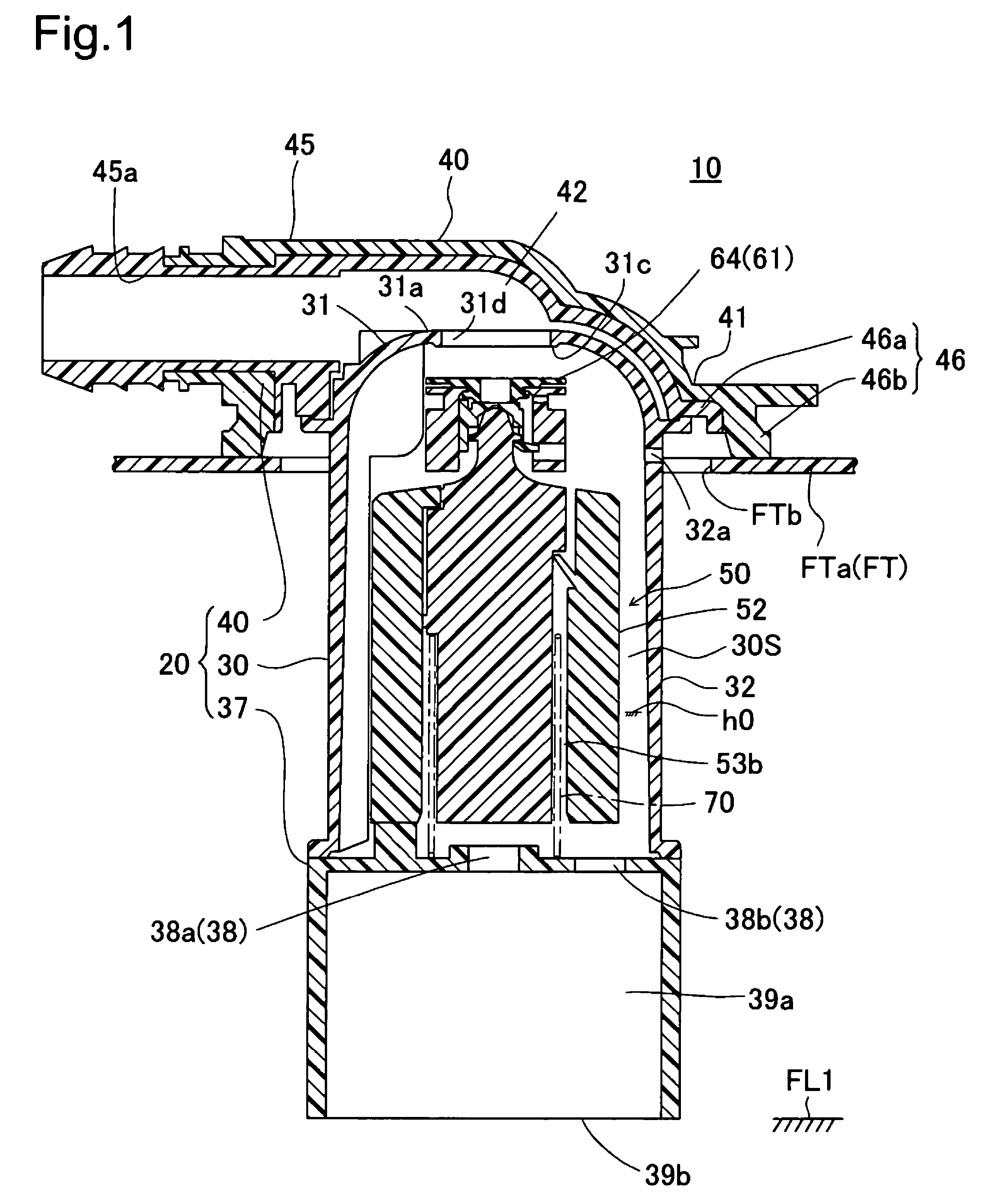
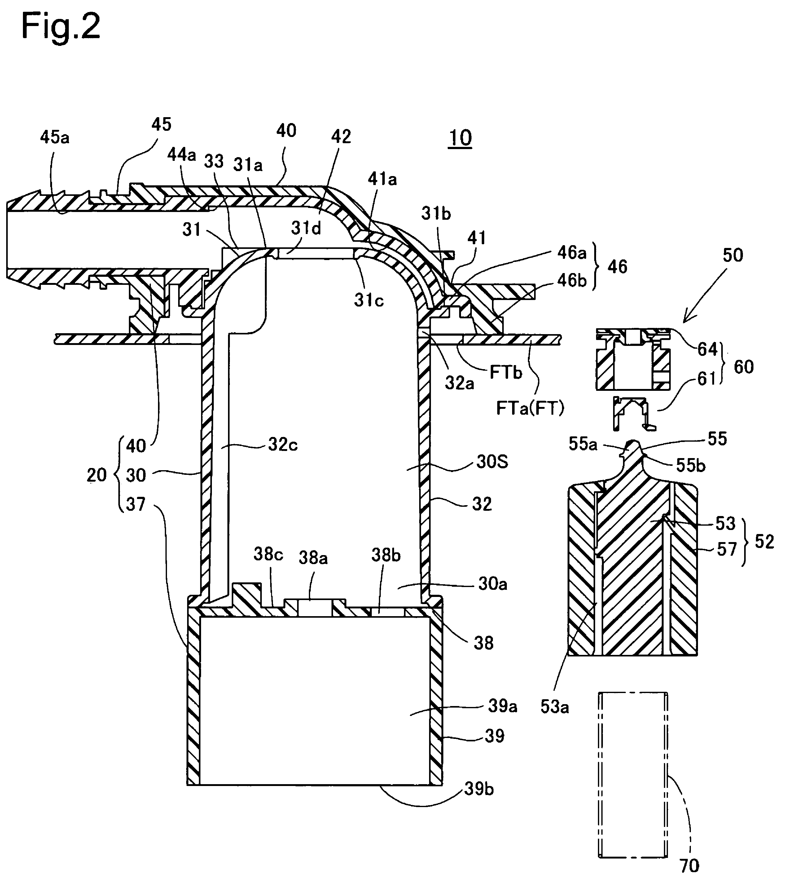
A tank flow path structure of a first embodiment can be suitably applied to a fuel cutoff valve attached to the top part of an automobile fuel tank. FIG. 1 is a cross section view showing the fuel cutoff valve 10. In FIG. 1, A fuel tank FT has its surface formed from a compound resin material containing polyethylene, and has an attachment hole FTb formed on a tank upper wall FTa. The fuel cutoff valve 10 is attached to the tank upper wall FTa in a state with its bottom part penetrating the attachment hole FTb. The fuel cutoff valve 10 comprises in its main constitution a casing 20, a float mechanism 50, and a spring 70. The casing 20 comprises a casing main body 30, a bottom member 37, and a cover 40, and the space enclosed by the casing main body 30 and the bottom member 37 is the valve chamber 30S, and the float mechanism 50 supported by the spring 70 is housed in the valve chamber 30S.

A connection conduit 42 connecting the valve chamber 30S to the outside is formed between the to...

second embodiment

FIG. 14 is a cross section view showing the top part of the casing 20B of the fuel cutoff valve 10B of the second embodiment, and FIG. 15 is a drawing viewing the cover 40B from the bottom. This embodiment has as its feature the constitution of providing a liquid trap chamber in which fuel leaked from the connection hole is temporarily pooled. Specifically, the fluid guide member 48B is provided standing beneath the cover inner wall 41Ba of the cover 40B (ventilation path main body). The fluid guide member 48B partitions the concave locations formed by the curved surface of the cover inner wall 41Ba, in other words that concave location is partitioned into the connection conduit 42B formed at the side direction from the center side of the cover 40B and the liquid trap chamber 47B formed at the outer periphery side of the connection conduit 42B. The fluid guide member 48B comprises an end portion 48Bc connected with the opening edge of the connection hole 31Bd, and furthermore, on th...
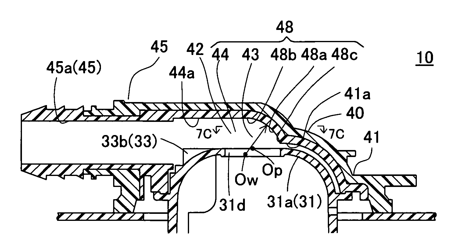
third embodiment

FIG. 16 is a cross section view showing the top part of the casing 20C of the fuel cutoff valve 10C of the This embodiment has as its feature the constitution of the liquid trap chamber 47C. Specifically, the liquid trap chamber 47C has a space formed between the top part of the casing main body 30C and the cover main body 41C of the cover 40C (ventilation path main body), in other words, it is surrounded by the top surface of the wall main body 31Ca that constitutes the conduit formation member 31C, the weir 35C provided standing from the wall main body 31Ca, the bottom surface of the cover main body 41C, and the end portion 48Cc of the bottom part of the fluid guide member 48C extending to the entire outer peripheral side of the connection hole 31Cd. The end portion 48Cc has a cylindrical shape, and is formed having the same inner diameter or a slightly larger inner diameter than that of the connection hole 31Cd so as to enclose the connection hole 31Cd. The liquid trap chamber 4...


PUM


Abstract

The fuel cutoff valve has a connection conduit that connects the connection hole to the approximately round shaped cross section tube passage. With the connection conduit, the connection hole and the flow path area are almost the same, and this comprises a curved passage part that makes the rising gas flow from the connection hole face in the horizontal direction, and a connection passage part that leads the gas flow from the curved passage part to the connection passage part. The fluid guide member that constitutes the curved passage part is a passage that has an inclined face that makes the rising gas flow that flows out from the connection hole face in the horizontal direction, and a passage upper surface formed from a flat surface continuous from the upper edge of the inclined face and arranged above the connection hole. The connection passage part is formed such that the cross section shape of the passage upper surface gradually faces the round shaped cross section of the tube passage.

Description

This application claims the benefit of and priority from Japanese Applications No. 2005-349765 filed Dec. 2, 2005 and No. 2006-138681 filed May 18, 2006, the contents of which are incorporated herein by reference.BACKGROUND OF THE INVENTION1. Field of the InventionThe present invention relates to a tank flow path structure that is mounted on the upper part of a fuel tank and is for connecting the inside of the fuel tank to the outside.2. Description of the Related ArtA tank flow path structure is disclosed in JP-A-2002-137641 and JP-A-11-315765, which is constructed in a fuel cutoff valve for ventilating the inside of the fuel tank to the outside. The fuel cutoff valve is mounted on the upper part of the fuel tank, and comprises a casing with a connection conduit connected to the outside (canister), and a float that rises and falls with the increase and decrease of buoyancy according to the fuel fluid level within the casing valve chamber. The fuel cutoff valve ensures ventilation b...

Claims


Application Information

Patent Timeline
Patent Type & Authority Patents(United States)
IPC IPC(8): F16K24/04
CPCF16K24/044Y10T137/3099
Inventor KANEKO, KENICHIRO
Owner TOYODA GOSEI CO LTD
Why Eureka
Try Eureka