Surface coating for chamber components used in plasma systems

a plasma system and surface coating technology, applied in vacuum evaporation coating, chemical vapor deposition coating, coatings, etc., can solve the problems of removing a substantial portion, substantially increasing plasma surface recombination rate, and no longer acceptable materials, so as to increase the efficiency of the system, increase the flow of excited plasma species, and reduce the effect of material recombination ra

Active Publication Date: 2017-02-02
ENTEGRIS INC
View PDF9 Cites 214 Cited by
  • Summary
  • Abstract
  • Description
  • Claims
  • Application Information

AI Technical Summary

Benefits of technology

[0005]Disclosed herein are surface coatings for plasma components that have the benefit of being robust against chemical and plasma physical attack in aggressive (e.g., fluorine-based) plasma environments. The coatings also provide low plasma surface recombination rates for active oxygen, nitrogen, fluorine, and hydrogen species when compared with other known surface treatments. The coatings can be applied to any plasma system component not requiring etching or plasma cleaning including but not limited to materials like quartz, aluminum, or anodized aluminum. Additionally, the efficiency of the system is increased by applying a non-reactive coating to system components thereby increasing the flow of excited plasma species to the processing chamber of the system.

Problems solved by technology

However, when halogen-containing, or other chemically more aggressive plasmas are being employed, these materials are no longer an acceptable choice.
While these materials have the advantage that they hold up better against chemical and physical plasma attack, the drawback is that they have substantially higher plasma surface recombination rates, hence removing a substantial portion of active oxygen, hydrogen and nitrogen plasma species from the plasma stream.
The removal of these species reduces the efficiency of the plasma process.

Method used


Image

  • Surface coating for chamber components used in plasma systems
  • Surface coating for chamber components used in plasma systems

Examples


example 1

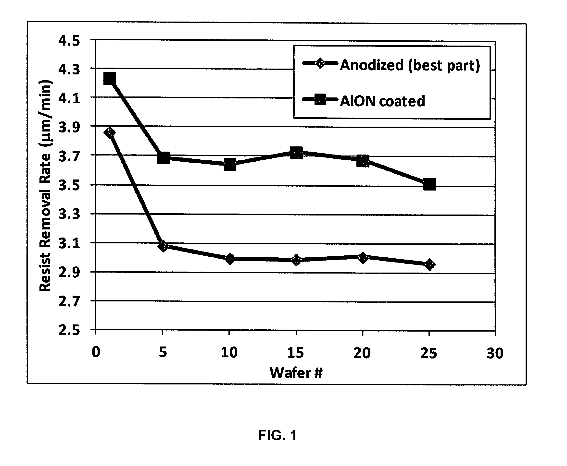
[0061]In this example, photoresist coated onto a 200 mm silicon substrate was exposed to plasma formed from oxygen and forming gas (3% hydrogen in nitrogen), using a Radiant Strip 220ES-IP plasma ashing tool, commercially available from Axcelis Technologies, Inc. A commercially available i-line photoresist was deposited onto the silicon substrate at a thickness of about 1.8 microns. The O2 / FG plasma chemistry was formed by flowing 90% of oxygen and 10% of forming gas at about 3.5 standard liters per minute (slm) into the plasma ashing tool at a pressure of about 1 Torr, a temperature of about 270° C., and a power setting of 2000 Watts.

[0062]Photoresist removal rate (also referred to as Ashing rate) and cross wafer uniformity of the O2 / FG plasma stripping process was determined after exposure of the photoresist to the respective plasma for 15 seconds. The Ashing rate was compared for two chamber baffle plate configurations:[0063](i) an anodized aluminum baffle plate with an optimized...

example 2

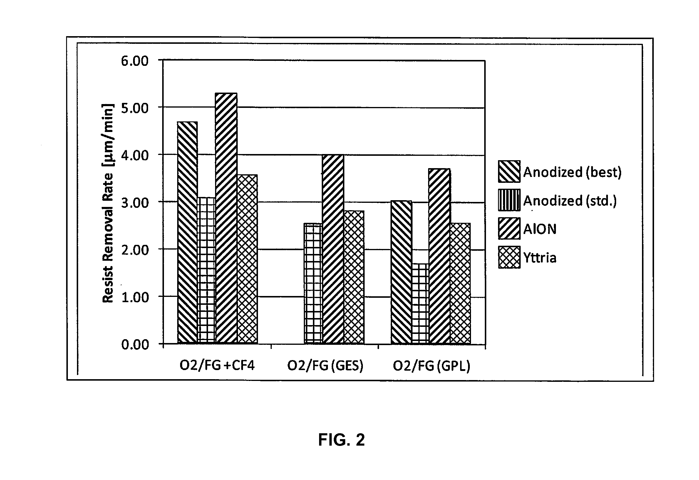
[0068]In this example, photoresist coated onto a 200 mm silicon substrate was exposed to various plasmas[0069](i) an O2 / FG plasma formed by flowing 90% of oxygen and 10% of forming gas into the plasma ashing tool at a pressure of about 1 Torr, a temperature of about 270° C., and a power setting of 2000 Watts;[0070](ii) an O2 / FG+CF4 plasma formed by flowing 90% of oxygen and 10% of forming gas, plus ˜0.15% CF4 into the plasma ashing tool at a pressure of about 1 Torr, a temperature of about 270° C., and a power setting of 2000 Watts.

and in two different plasma cleaning systems:[0071](i) a Radiant Strip 220ES-IP plasma ashing tool, commercially available from Axcelis Technologies, Inc.;[0072](ii) a Radiant Strip 220 plasma ashing tool, commercially available from Axcelis Technologies, Inc.

[0073]and for 4 different plasma tool baffle configurations:[0074](i) an optimized anodized aluminum baffle;[0075](ii) a standard anodized aluminum baffle;[0076](iii) an aluminum oxynitride coated al...


PUM

PropertyMeasurementUnit
temperaturesaaaaaaaaaa
thickaaaaaaaaaa

Abstract

Disclosed herein are surface coatings for plasma components that have the benefit of being robust against chemical and plasma physical attack in aggressive (e.g., fluorine-based) plasma environments. The coatings also provide low plasma surface recombination rates for active oxygen, nitrogen, fluorine, and hydrogen species when compared with other known surface treatments. The coatings can be applied to any plasma system component not requiring etching or plasma cleaning including but not limited to materials like quartz, aluminum, or anodized aluminum. Additionally, the efficiency of the system is increased by applying a non-reactive coating to system components thereby increasing the flow of excited plasma species to the plasma chamber of the system.

Description

RELATED APPLICATIONS[0001]This application claims the benefit of U.S. Provisional Patent Application No. 61 / 907,214 filed Nov. 21, 2013, the disclosure of which is hereby incorporated by reference herein in its entirety.FIELD OF THE DISCLOSURE[0002]The disclosure relates generally to plasma systems and more specifically to coatings for tooling and fixtures in plasma systems.BACKGROUND OF THE DISCLOSURE[0003]The present disclosure generally relates to coatings of parts that are used in plasma systems. Parts that are in direct contact with the plasma are subject to chemical attack, ion bombardment, UV irradiation, large temperature variations and gradients, as well as electrical fields. Preferred plasma system parts are made of aluminum or quartz, because they have the lowest plasma surface recombination rates for active oxygen, nitrogen and hydrogen species. However, when halogen-containing, or other chemically more aggressive plasmas are being employed, these materials are no longer...

Claims


Application Information

Patent Timeline
Patent Type & Authority Applications(United States)
IPC IPC(8): H01J37/32C23C14/08C23C14/06
CPCH01J37/32495C23C14/083C23C14/0676C23C14/35C23C14/30C23C14/3485C23C16/308C23C16/405C23C16/4404C23C16/505
Inventor WALDFRIED, CARLO
Owner ENTEGRIS INC
Why Eureka
Try Eureka