Toothbrush employing an acoustic waveguide

Inactive Publication Date: 2005-05-05
UNIV OF WASHINGTON
View PDF5 Cites 199 Cited by
  • Summary
  • Abstract
  • Description
  • Claims
  • Application Information

AI Technical Summary

Benefits of technology

[0026] The present invention fulfills these and other related needs by providing toothbrushes, including power and manual toothbrushes, that employ an acoustic waveguide, either alone or in combination, with an ultrasonic transducer and/or sonic component to achieve improved plaque and stain removal and user experience. Accordingly, within certain embodiments, the present invention provides power toothbrushes having one or more acoustic waveguide that is capable of propagating and possibly focusing acoustic waves transmitted by an ultrasonic transducer into the dental fluid, thereby inducing cavitation of microbubbles and, in addition or alternately, inducing acoustic streaming, with a consequent improvement in the loosening and removal of dental plaque from dental surfaces and interproximal regions. When used in combination with a sonic component, the acoustic waveguide can, additionally or alternatively, be made to vibrate such that the acoustic waveguide contributes to enhanced fluid flow in the oral cavity and to the formation of microbubbles in the dental fluid, beyond the reach of the acoustic waveguide and/or toothbrush head bristle tips. When used in combination with a sonic component, the enhanced bubbly fluid flow generated by the acoustic waveguide can, additionally or alternatively, work synergistically with the ultrasound transmitted through the acoustic waveguide to further facilitate plaque and stain removal beyond the reach of the acoustic waveguide and/or toothbrush head bristle tips.
[0027] In an embodiment of the present invention, an ultrasonic transducer is utilized at the toothbrush head, at the base of and in operable proximity to an acoustic waveguide or, alternatively, mechanically coupled to the toothbrush head from within the toothbrush handl

Problems solved by technology

Previous attempts at creating ultrasonic toothbrushes failed to exploit microbubble formation in dental fluid for purposes of facilitating plaque removal, or failed to consider microbubbles and macrobubbles as a potential impediment to ultrasound propagation beyond the bristle tips.
Because conventional toothbrush

Method used


Image

  • Toothbrush employing an acoustic waveguide
  • Toothbrush employing an acoustic waveguide
  • Toothbrush employing an acoustic waveguide

Examples


example 1

Design and Construction of a Combined Sonic and Ultrasonic toothbrush

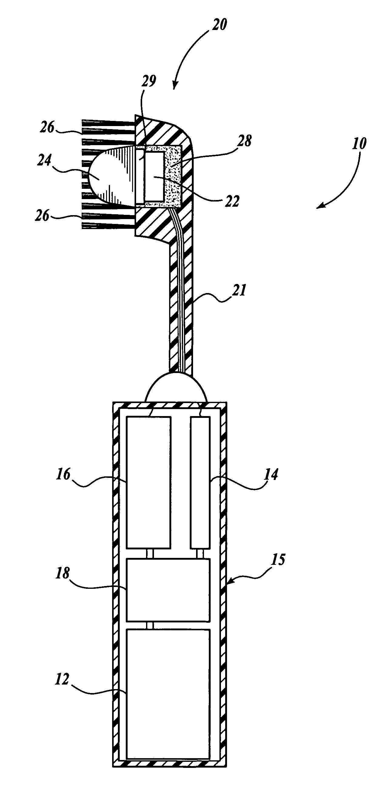
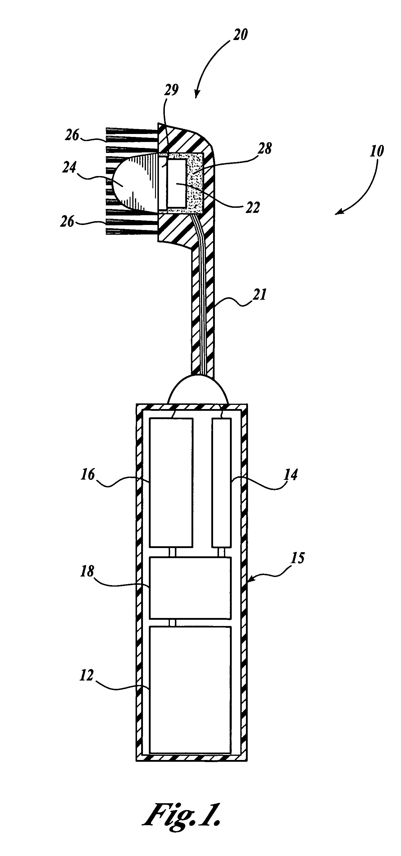
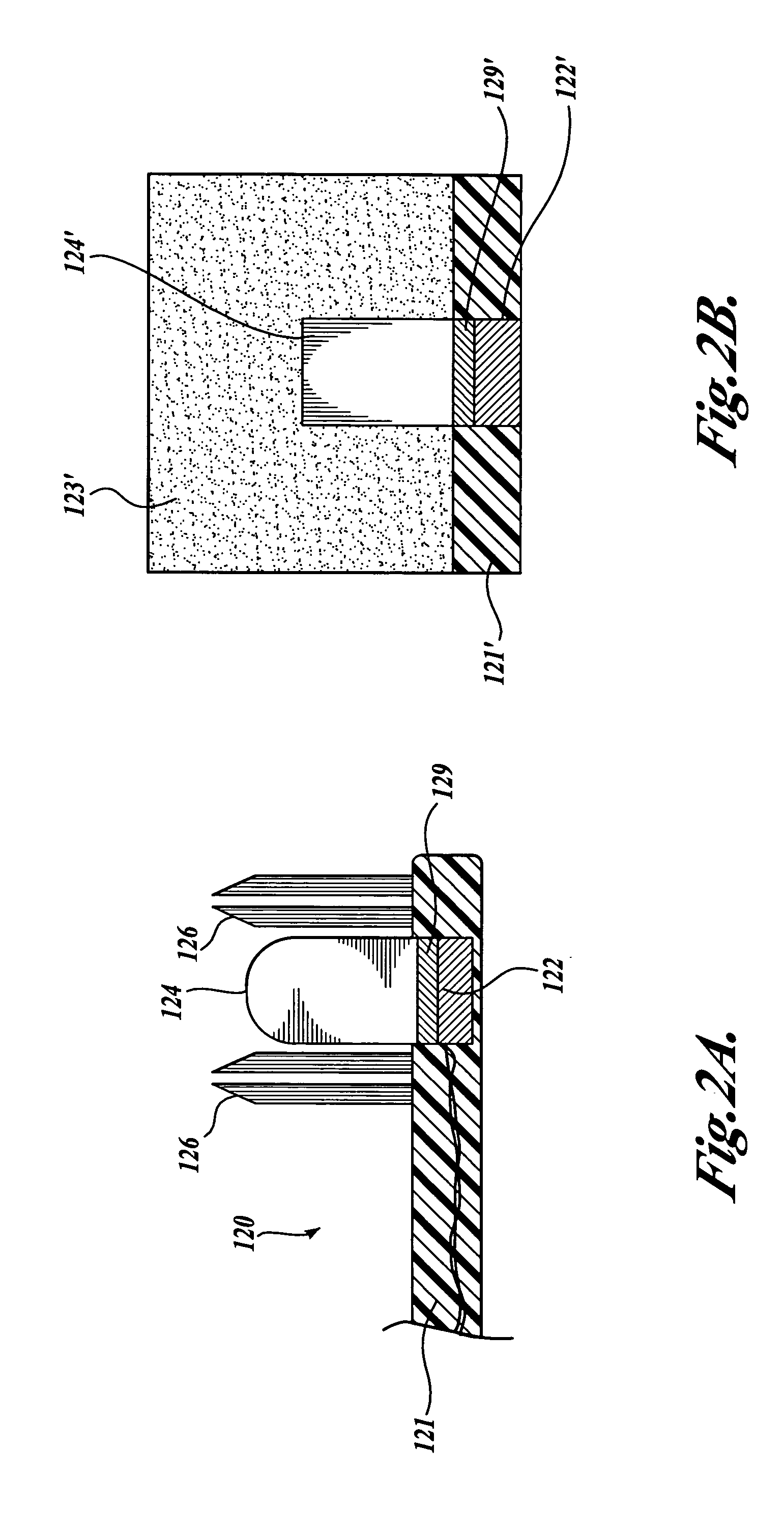
[0116] Prototype power toothbrushes were generated by replacing internal bristle tufts of commercially available power toothbrushes with an ultrasonic transducer and acoustic waveguide. Ultrasonic transducers employed in these prototype toothbrushes had significant power output within the frequency range of about 150 to about 510 kHz that was sufficient to stimulate the formation of an acoustically significant bubble population susceptible to resonant stimulation by energy emitted by the ultrasonic transducer. A polymer waveguide was molded onto the toothbrush head in operable proximity to the ultrasonic transducer and positioned such that ultrasonic waves generated by the ultrasonic transducer were propagated and focused.

example 2

Ultrasonic Imaging and Plague Removal by an Exemplary Ultrasonic Power Toothbrush

[0117] This example discloses ultrasound imaging and plaque removal data collected for one of the prototype power toothbrushes described in Example 1.

[0118] In order to demonstrate the improved performance of a power toothbrush employing an ultrasonic transducer in combination with an acoustic waveguide, Doppler, and B-mode data were collected for a prototype ultrasonic toothbrush with and without incorporating an acoustic waveguide. FIG. 5A presents an ultrasound image of an ultrasonic toothbrush without an acoustic waveguide. Doppler data show fluid flow (within box) and B-mode data highlight acoustic backscatter (outside of box) at the bristle tips (BT) and bristle plate (BP) at bottom of bristles. FIG. 5B presents the same ultrasonic toothbrush with moving bristles powered by a sonic component. These data reveal that fluid flow (FF) beyond the bristle tips is not detectable even though the bristle...

example 3

Measurement of Physical Parameters of an Exemplary Ultrasonic Power Toothbrush Employing an Acoustic Waveguide

[0121] This example discloses measurements of physical parameters of an exemplary ultrasonic power toothbrush of the present invention.

[0122] In order to compare the effectiveness of various acoustic waveguide geometries, the transmitting pressures for a flat, unfocused elastomeric / silicone polymer wedge waveguide was compared to the transmitting pressures for a focused elastomeric / silicone polymer wedge waveguide. The plot of acoustic pressure levels at the tip of each acoustic waveguide presented in FIG. 6 demonstrates an approximately three-fold increase in transmitting pressure for a focused waveguide (˜1.5 MPa tip pressure) versus an unfocused waveguide (˜0.5 MPa tip pressure).

[0123] The absorption of ultrasound transmitted through a model dental fluid / bubble emulsion was measured as a function of ultrasonic frequency in the 30 to 700 kHz frequency range. Ultrasonic ...


PUM


Abstract

A power toothbrush (10) is disclosed having a handle (15) containing a rechargeable battery (12), an ultrasonic drive circuit (14), a sonic component (16) such as a motor, and a control unit (18). The handle is connected to a toothbrush head (20) preferably having a plurality of bristles (26) and an ultrasonic transducer (22) that is operatively connected to a waveguide (24) that extends from the toothbrush head generally adjacent the bristles. The waveguide facilitates the transmission of acoustic energy into the dental fluid. It is contemplated that the waveguide may be utilized in manual or power toothbrushes, and in a combination without the sonic component, or in a combination without the ultrasonic transducer. Toothbrushes disclosed herein achieve improved plaque and stain removal from the teeth as well as interproximal and subgingival regions, while enhancing the user experience, massaging the gums, and stimulating dental tissue.

Description

CROSS-REFERENCE TO RELATED APPLICATION [0001] This application claims the benefit of U.S. Provisional Patent Application No. 60 / 517,638, filed on Nov. 4, 2003, the disclosure of which is hereby expressly incorporated by reference, and priority from the filing date of which is hereby claimed under 35 U.S.C. § 119.FIELD OF THE INVENTION [0002] The present invention relates generally to the fields of toothbrushes and, more specifically, to toothbrushes that employ acoustic mechanisms. BACKGROUND OF THE INVENTION [0003] Existing power toothbrushes, even the most effective, leave clinically significant plaque at tooth-contact surfaces, at the gingival-tooth contact points, below the gingiva and beyond the direct reach of the bristles or other toothbrush components. Previous attempts at creating ultrasonic toothbrushes failed to exploit microbubble formation in dental fluid for purposes of facilitating plaque removal, or failed to consider microbubbles and macrobubbles as a potential impe...

Claims


Application Information

Patent Timeline
IPC IPC(8): A46B15/00A61CA61C17/20A61C17/22A61C17/34
CPCA46B15/0002A46B15/0028A61C17/3481A61C17/20A46B2200/1066A61C17/22
Inventor MOURAD, PIERRE D.OLSON, FRANCIS G.THOMPSON, ROGER LEESEAWALL, JASON L.
Owner UNIV OF WASHINGTON
Why Eureka
Try Eureka