Systems And Methods For Removing Obstructive Matter From Body Lumens And Treating Vascular Defects

a technology of body lumens and obstructive matter, applied in the field of medical devices and methods, can solve the problems of embolic stroke, increased risk of intracerebral hemorrhage and other hemorrhagic complications, and bleeding into brain tissue and resultant infarction of brain tissu

Inactive Publication Date: 2012-04-26
TYCO HEALTHCARE GRP LP
View PDF3 Cites 207 Cited by
  • Summary
  • Abstract
  • Description
  • Claims
  • Application Information

AI Technical Summary

Benefits of technology

[0016]Still further in accordance with the invention there is provided a method for removing obstructive matter from a body lumen, such method comprising the steps of: a) inserting a catheter that has a proximal portion, a distal portion, a lumen and a distal end opening, said catheter being transitionable from a first configuration wherein the distal portion has a first outer diameter that is smaller than the outer diameter of the proximal portion and a second configuration wherein the distal portion is expanded to a second outer diameter that is larger than the first outer diameter and no larger than the outer diameter of the proximal portion; b) positioning the catheter, while in the first configuration, such that its distal end opening is within a body lumen; c) causing the catheter to transition from the first configuration to the second configuration; d) moving obstructive matter through the distal end opening and into the lumen of the catheter; and e) removing the catheter along with the obstructive matter that has been moved into the lumen of the catheter. In some embodiments, negative pressure may be applied through the lumen of the catheter to aspirate obstructive matter through the distal end opening and into the lumen of the catheter. In some embodiments Step D of the method may comprise advancing an obstructive matter moving device (e.g., an embolectomy device) from the catheter and using the obstructive matter moving device to move obstructive matter through the distal end opening and into the lumen of the catheter. One non-limiting example of the types of obstructive matter moving device that may be used is a device having an expandable element that is expanded within the body lumen such that obstructive matter becomes entrained in or engaged by the expandable element in a manner that allows it to thereafter move some or all of the obstructive matter. Such expandable element is then retracted, along with obstructive matter that has become entrained in or engaged by the expandable member, through the distal end opening and into the lumen of the catheter. In some cases the method may further include the step of delivering a therapeutic substance. For example, in cases where the obstructive matter comprises thrombus, a thrombolytic agent or other substance that will dissolving some of the thrombus and / or deter adherence of the thrombus to a wall of the body lumen may be delivered. In some embodiments where an obstructive matter moving device is used, such obstructive matter moving device is used to move the obstructive matter into the catheter, the obstructive matter moving device may initially be used to canalize or compress the obstructive matter in a manner that improves blood flow through or around the obstructive matter for a period of time and, thereafter, is used to move at least some of the obstructive matter through the distal opening and into the lumen of the catheter.
[0017]Still further in accordance with the present invention, there is provided a method for increasing flow of a body fluid through an obstructed body lumen, such method comprising the steps of: a) inserting a catheter that has a proximal portion, a distal portion, a lumen and a distal end opening, said catheter being transitionable from a first configuration wherein the distal portion has a first outer diameter that is smaller than the outer diameter of the proximal portion and a second configuration wherein the distal portion is expanded to a second outer diameter that is larger than the first outer diameter and no larger than the outer diameter of the proximal portion; b) positioning the catheter, while in the first configuration, such that its distal end opening is within a body lumen; c) causing the catheter to transition from the first configuration to the second configuration; and d) using the catheter to deliver a treatment that restores or improving flow of a body fluid through an obstructed body lumen. In some embodiments, the treatment delivered may comprise the delivery of a therapeutic substance (e.g., a thrombolytic agent) of a type and in an amount that is effective to improve flow of body fluid through the body lumen. In some embodiments, the treatment delivered may comprise use of a device that canalizes or compresses obstructive matter in a manner that improves flow of body fluid through or around the obstructive matter.
[0019]In certain embodiments, the therapeutic catheter can be used to inject angiographic dye into the lumen of a vessel within which the catheter is disposed. Dye injection lumens can be operably connected to dye exit ports at the distal end of the therapeutic catheter. Dye injection lumens can also be operably connected to dye exit ports disposed at intervals along the length of the catheter near its distal end. The dye injection lumens can be operably connected to dye injection ports at the proximal end of the catheter, which are accessible to connection to syringes or other liquid pressure injection devices. The catheter can be routed through an obstruction, for example over a guidewire. Dye can be injected so that it flows through the distal dye exit port and into the vessel lumen. Dye can further be injected such that it flows from the proximal dye exit ports. Dye exit ports disposed, or embedded, within the obstruction will be blocked and prevent dye exit. However dye exit ports located proximally to the obstruction will permit free flow of dye into the vessel lumen. The visual gap between the dye that exited from the distal ports and the more proximal ports can provide an indication of the extent or length of the obstruction, such as a clot or thrombus, within the vessel lumen. Flow restrictions within the guide catheter can be added to optimize flow from the side ports given the low resistance to flow out the distal end. Such flow restrictors can restrict, or completely block, flow out the distal end of the catheter and increase flow through side ports. Side ports disposed distally to the obstruction can serve the same function as an open central lumen port.
[0021]The therapeutic expandable guide catheter can be advanced toward and through an obstruction such as a clot or region of spasm within a vessel. The obstruction is penetrated by the removable obturator or guidewire and is followed by the radially collapsed distal end of the expandable guide catheter. The obturator is removed once the obstruction is fully penetrated and the distal end of the expandable region is securely within unobstructed vessel lumen. The translation dilator is next advanced distally to expand the distal, expandable region and the window in the side wall of the translation dilator is aligned with the port or window in the proximal portion of the expandable guide catheter. In other embodiments, the obturator can remain within the translation dilator while it is being advanced distally to expand the distal, radially expandable region. Blood flow through the vessel obstruction can be restored in this way since blood can flow into the window or port within the sidewall of the expandable guide catheter and flow out through the open distal end of the central lumen of the translation dilator. In other embodiments, blood flow can also be restored in the reverse direction.

Problems solved by technology

Hemorrhagic stroke often occurs due to rupture of an aneurysm or arteriovenous malformation (AVM), causing bleeding into the brain tissue and resultant infarction of brain tissue.
Those emboli can pass to the brain and cause an embolic stroke.
However, treatment with systemic t-PA is associated with increased risk of intracerebral hemorrhage and other hemorrhagic complications.
However, removal of emboli using such catheters carries attendant potential problems.
One such problem occurs when advancing the catheter through the clot dislodges material to a more remote site where removal may become more difficult or impossible.
Although neurointerventional devices and procedures have advanced, there remains a need for expeditious restoration of distal flow to blocked, or stenotic, cerebrovascular vessels, which can lead to severe neurological deficit or patient death.

Method used


Image

  • Systems And Methods For Removing Obstructive Matter From Body Lumens And Treating Vascular Defects
  • Systems And Methods For Removing Obstructive Matter From Body Lumens And Treating Vascular Defects
  • Systems And Methods For Removing Obstructive Matter From Body Lumens And Treating Vascular Defects

Examples


Embodiment Construction

[0102]The inventions disclosed herein may be embodied in other specific forms without departing from its spirit or essential characteristics. The described embodiments are to be considered in all respects only as illustrative and not restrictive. The scope of the inventions is therefore indicated by the appended claims rather than the foregoing description. All changes that come within the meaning and range of equivalency of the claims are to be embraced within their scope.

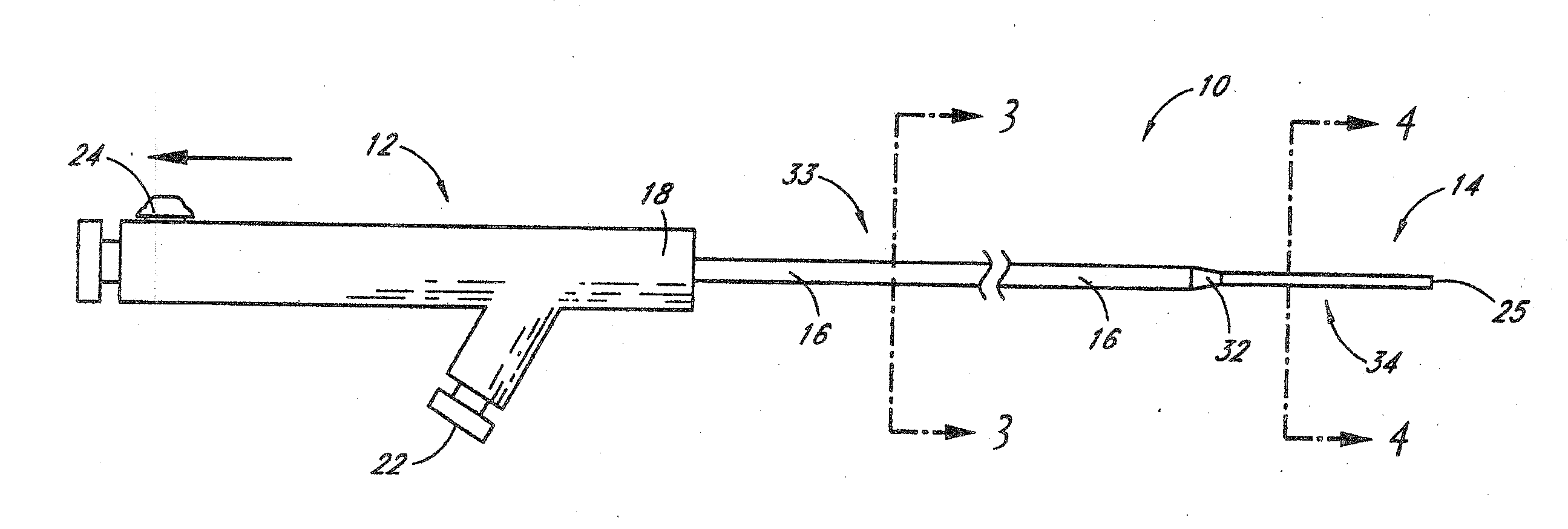
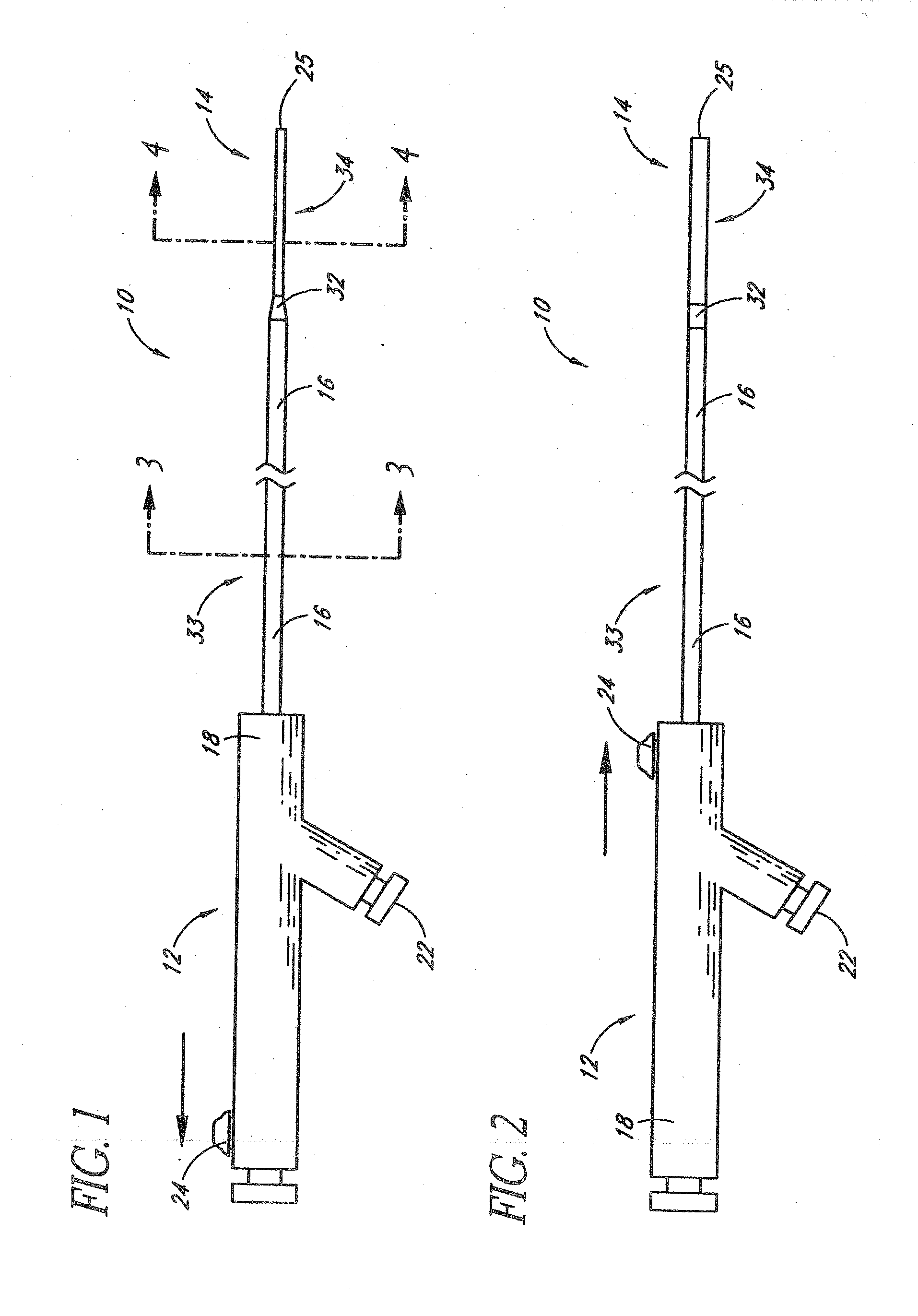
[0103]As used herein, the terms proximal and distal refer to a direction or a position along a longitudinal axis of a catheter or medical instrument. Proximal refers to the end of the catheter or medical instrument closer to the operator, while distal refers to the end of the catheter or medical instrument closer to the patient. For example, a first point is proximal to a second point if it is closer to the operator end of the catheter or medical instrument than the second point. The measurement term French, abbre...


PUM


Abstract

Systems and methods for removing obstructions from, delivering implantable devices or substances in or near and / or restoring flow through body lumens, such as blood vessel lumens. A catheter having a proximal portion of a first diameter and a distal portion of a second diameter (smaller than the first diameter) is advanced into a body lumen. The distal portion of the catheter is caused to expand to a diameter that is larger than the second diameter but no larger than the first diameter. A working device is then advanced out of the distal end of the catheter and used to remove obstructive matter, deliver an implantable device or substance and / or restore flow. The distal portion can be reduced in diameter prior to removal from the body.

Description

RELATED APPLICATIONS[0001]This PCT international application claims priority to U.S. patent application Ser. No. 12 / 343,374, filed Dec. 23, 2008, which is a continuation-in-part of co-pending U.S. patent application Ser. No. 11 / 936,632 filed Nov. 7, 2007 which is a continuation of U.S. patent application Ser. No. 10 / 623,875 filed Jul. 21, 2003 and now issued as U.S. Pat. No. 7,309,334 which claims priority to U.S. Provisional Patent Application No. 60 / 398,071 filed Jul. 23, 2002, the entire disclosure of each such application being expressly incorporated herein by reference.FIELD OF THE INVENTION[0002]The present invention relates generally to medical devices and methods and more particularly to catheter-based systems and methods useable for removing obstructions from or treating defects in blood vessels, such as blood vessels of the brain.BACKGROUND OF THE INVENTION[0003]Stroke is a common cause of death in the United States and disabling neurologic disorder. Approximately 700,000 ...

Claims


Application Information

Patent Timeline
Patent Type & Authority Applications(United States)
IPC IPC(8): A61B17/22A61M29/00
CPCA61B17/12118A61B2017/12054A61B17/12186A61B17/22A61B17/3439A61B2017/00867A61B2017/22042A61B2017/22044A61B2017/22094A61B2017/2212A61M25/0021A61M25/0023A61M25/0043A61M27/002A61M2025/0024A61B17/1214A61B17/221A61B17/320725A61B2017/22001A61B2217/005A61M25/0074A61B5/6858A61B2017/22041A61M25/0026
Inventor LENKER, JAY A.STRAUSS, BRIAN M.SHIMADA, LYNN MIYEKO
Owner TYCO HEALTHCARE GRP LP
Why Eureka
Try Eureka