Heat conversion device

a heat conversion device and heat conversion technology, applied in the direction of lighting and heating apparatus, machine operation mode, heating type, etc., can solve the problems of reduced heat conversion efficiency, increased power consumption and noise, and reduced performance as a dehumidifier, so as to achieve high efficiency and reduce power consumption , the effect of heat conversion efficiency can be maximized

Active Publication Date: 2015-08-20
LG INNOTEK CO LTD
View PDF1 Cites 1 Cited by
  • Summary
  • Abstract
  • Description
  • Claims
  • Application Information

AI Technical Summary

Benefits of technology

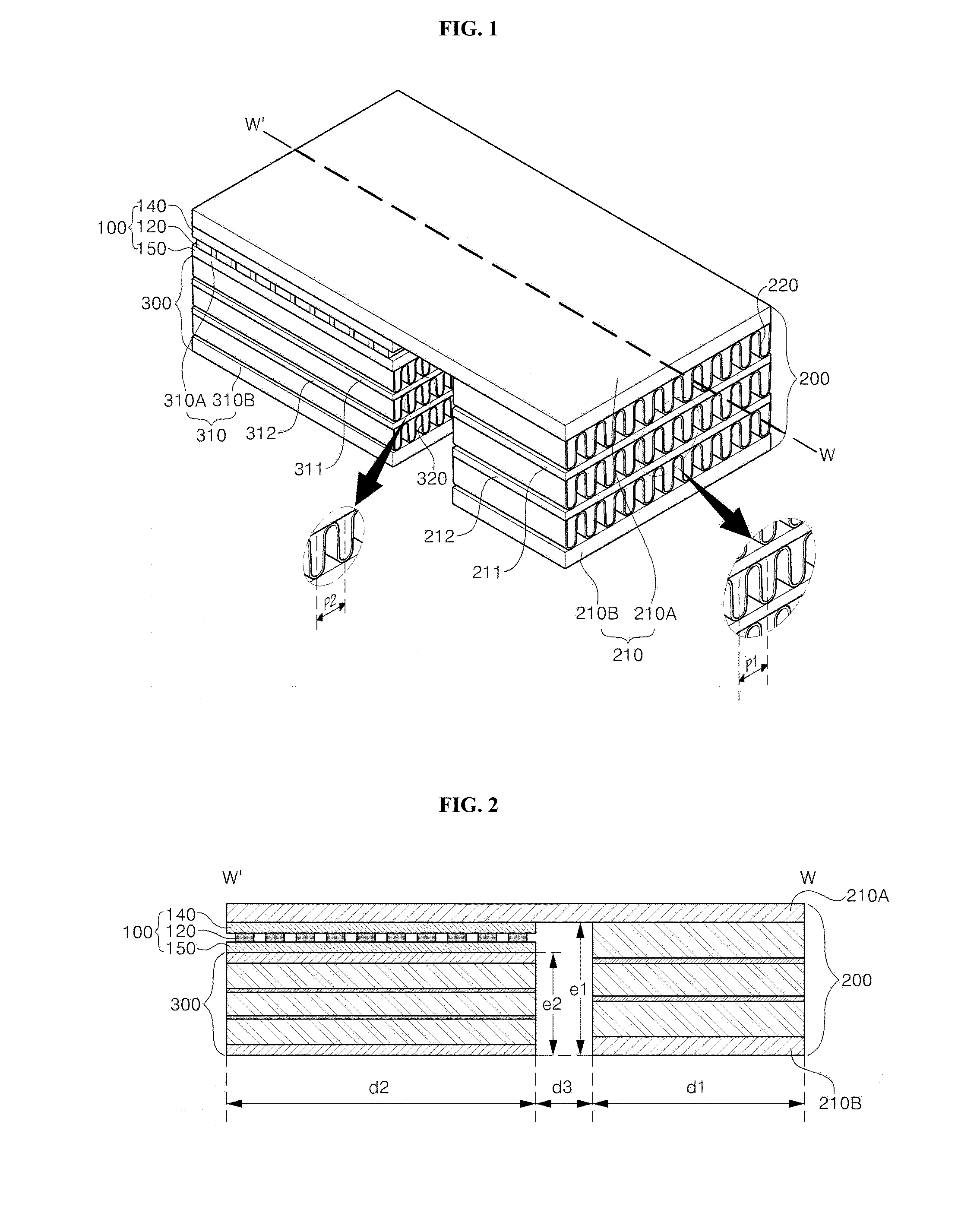
[0007]The present invention has been made keeping in mind the above problems, an aspect of embodiments of the present invention provides a heat conversion device capable of implementing a heat conversion function of high efficiency in spite of low power consumption by disposing a heat absorption module and a heat emission module in a horizontal direction in a structure of a heat exchange device to which a thermoelectric module is applied, and by implementing a heat conversion effect for air while maintaining a desired air volume and air velocity without flow path resistance.
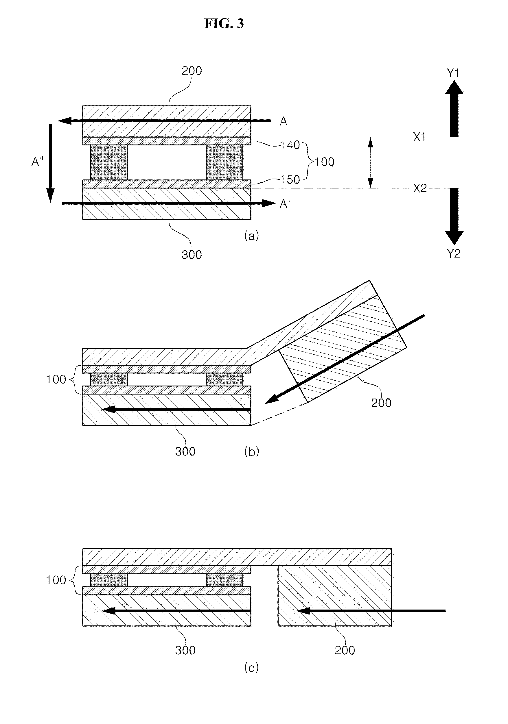
[0008]According to an aspect of an embodiment of the present invention, a heat conversion device may include: a first module including a first heat conversion member; a second module including a second heat conversion member that introduces air passing through the first module to perform heat conversion; and a thermoelectric module that comes into contact with the first module and the second module to control a heat conversion function, wherein the first module and the second module are arranged in one side direction based on the thermoelectric module. That is, the first module and the second module are disposed in a horizontal direction rather than being disposed up and down based on the thermoelectric module so that the flow path resistance of entering air can be reduced and heat conversion efficiency can be maximized.

Problems solved by technology

However, in this case, even though the air entered from the thermoelectric into the heat absorption part is primarily dehumidified, and the air is then introduced to the heat emission part arranged at an upper portion of the thermoelectric element so as to be dried, it is problematic in that dehumidification efficiency is reduced because the flow of air is increased and flow path resistance is generated.
In order to settle this problem, there is a way to entirely make the flow of air strong by increasing the strength of entering air, but this way leads to an increase of power consumption and an increase in noise.
Thus, it is problematic in that performance as a dehumidifier is very reduced.

Method used


Image

  • Heat conversion device
  • Heat conversion device
  • Heat conversion device

Examples


Embodiment Construction

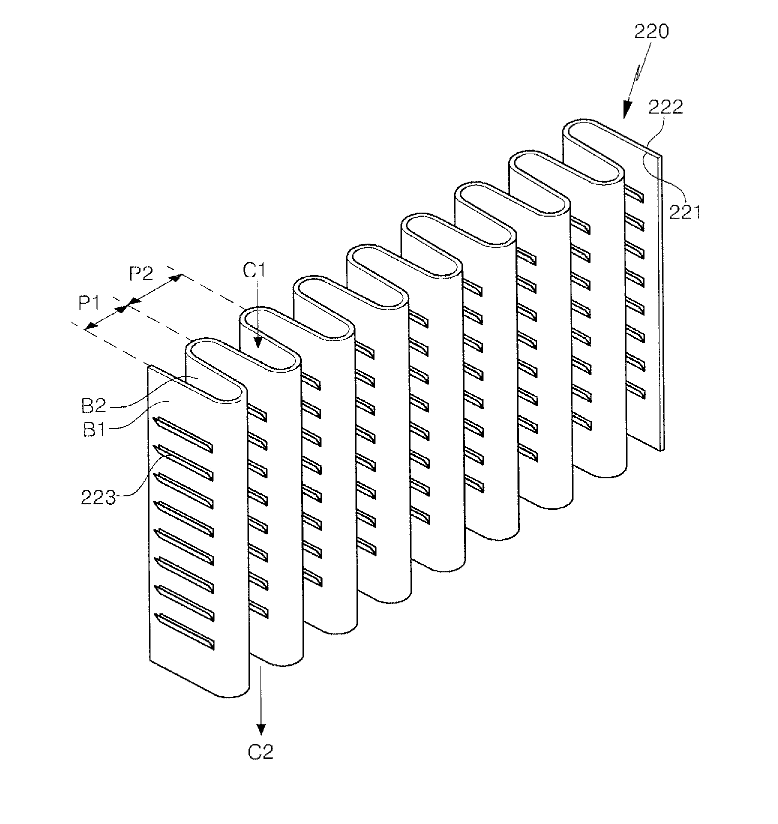
[0017]Hereinafter, the configurations and operations according to embodiments of the present invention will be described in detail with reference to the accompanying drawings. The present invention may, however, be embodied in different forms and should not be construed as limited to the embodiments set forth herein. In the explanation with reference to the accompanying drawings, regardless of reference numerals of the drawings, like numbers refer to like elements through the specification, and repeated explanation thereon is omitted. Terms such as a first term and a second term may be used for explaining various constitutive elements, but the constitutive elements should not be limited to these terms. These terms are only used for the purpose for distinguishing a constitutive element from other constitutive element. Furthermore, the elements having the similar functions and operations of the drawings are given the same reference numerals. As used herein, the singular forms are inte...


PUM


Abstract

Provided is a heat conversion device including a thermoelectric element, the heat conversion device capable of implementing a heat conversion function of high efficiency in spite of low power consumption by disposing a heat absorption module and a heat emission module in a horizontal direction in a structure of a heat exchange device to which a thermoelectric module is applied, and by implementing a heat conversion effect for air while maintaining a desired air volume and air velocity without flow path resistance.

Description

CROSS-REFERENCE TO RELATED APPLICATION[0001]This application claims the benefit under 35 U.S.C. §119 Korean Patent Application No. 10-2014-0017321, filed Feb. 14, 2014, which is hereby incorporated by reference in its entirety.BACKGROUND[0002]1. Field of the Invention[0003]Embodiments of the present invention relate to a heat conversion device including a thermoelectric element.[0004]2. Description of the Related Arts[0005]In general, a thermoelectric element including a thermoelectric device has a structure in which a PN junction pair is formed by bonding a p-type thermoelectric material and an n-type thermoelectric material between metal electrodes. When a temperature difference is provided between the materials of this PN junction pair, electric power is generated by the Seebeck effect so that a thermoelectric element can serve as a power generating device. Also, the thermoelectric element may be used as a temperature controlling device by the Peltier effect in which one material...

Claims


Application Information

Patent Timeline
Patent Type & Authority Applications(United States)
IPC IPC(8): F25B21/04
CPCF24F5/0042H10N10/13F25B21/04
Inventor CHO, YONG SANG
Owner LG INNOTEK CO LTD
Why Eureka
Try Eureka