Check valve and receptacle structure

a technology of receptacle and check valve, which is applied in the direction of valve housing, container discharging methods, separation processes, etc., can solve the problems of complex manufacturing process, and achieve the effect of improving durability and simplifying the manufacturing process

Active Publication Date: 2018-07-24
TOYOTA JIDOSHA KK +1
View PDF24 Cites 1 Cited by
  • Summary
  • Abstract
  • Description
  • Claims
  • Application Information

AI Technical Summary

Benefits of technology

[0007]According to the check valve of this aspect, the sealing portion formed in the outer surface of the valve housing seals the casing flow path between the valve housing and the casing, and positions the valve housing in the radial direction perpendicular to the axial direction with respect to the casing. Therefore, the structure for positioning the valve housing within the casing and the structure for forming the flow path which leads the fluid in the axial direction on the outer surface of the valve housing can be simplified, thereby simplifying the entire structure of the check valve. Here, since the casing flow path through which the fluid passed through the communicating hole flows in the axial direction of the valve housing is formed between the casing and the valve housing, a pressure loss in the check valve can be reduced.
[0009]According to the check valve of this aspect, since the sealing operation of the casing flow path and the positioning operation of the valve housing in the radial direction can be performed simultaneously, the manufacturing process can be simplified. Note that, by pinching the protruded portion between the two adjacent casing members, not only the positioning in the radial direction but a positioning in the axial direction can also be simultaneously performed as the positioning of the valve housing with respect to the casing. Further, since the pair of tapered portions formed in the protruded portion contact the two adjacent casing members, respectively, it becomes easy to secure a space which serves as the casing flow path between the outer surface of the valve housing and the inner surface of the casing.
[0010](3) In the check valve according to the above aspect, the casing and the valve housing may be made of metal. According to the check valve of this aspect, since the casing flow path can be metal / sealed, the durability of the sealing structure can be improved, compared with a case where the sealing is secured by a sealing member made of a resin or rubber.
[0012]According to the check valve of this aspect, an exposure of components of the check valve other than the surfaces of the casing and the valve housing to the casing flow path can be reduced. Therefore, a flow path resistance in the check valve can be reduced, thereby improving an effect of reducing the pressure less.
[0014](6) According to another aspect of the invention, there is provided a receptacle structure mounted to a housing of a device that includes a hydrogen tank placed therein, the receptacle structure having a filling port that forms an end structure of a flow path communicating with the hydrogen tank and being connected with a hydrogen discharging part of a hydrogen supply device to fill hydrogen into the hydrogen tank. The receptacle structure comprises the check valve in accordance with any one of (1) to (5), and an interposition member that is placed between the check valve and the housing of the device. The casing of the check valve is made of austenite stainless steel. The interposition member is made of a less noble metal than the austenite stainless steel. According to the receptacle structure of this aspect, since a corrosion of the interposition member is easier, a corrosion of the casing can be reduced. Therefore, a stress corrosion cracking of the casing made of austenite stainless steel under a high-stress and high-corrosive atmosphere can be prevented, and the durability can be improved.

Problems solved by technology

In other words, it is necessary to form the particular structure for forming the flow path by cutting etc., thereby requiring a complicated manufacturing process.

Method used


Image

  • Check valve and receptacle structure
  • Check valve and receptacle structure
  • Check valve and receptacle structure

Examples


modification 1 (

Modification of Sealing Portion)

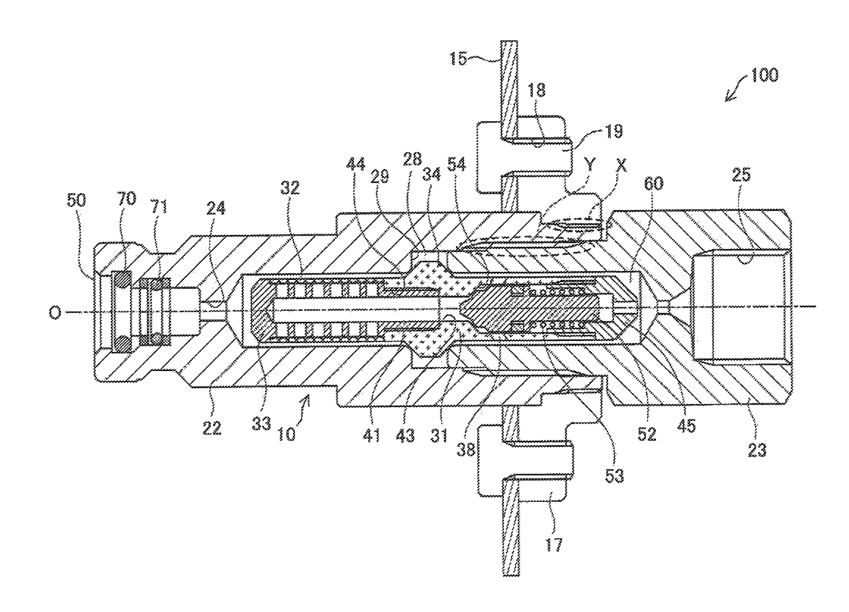
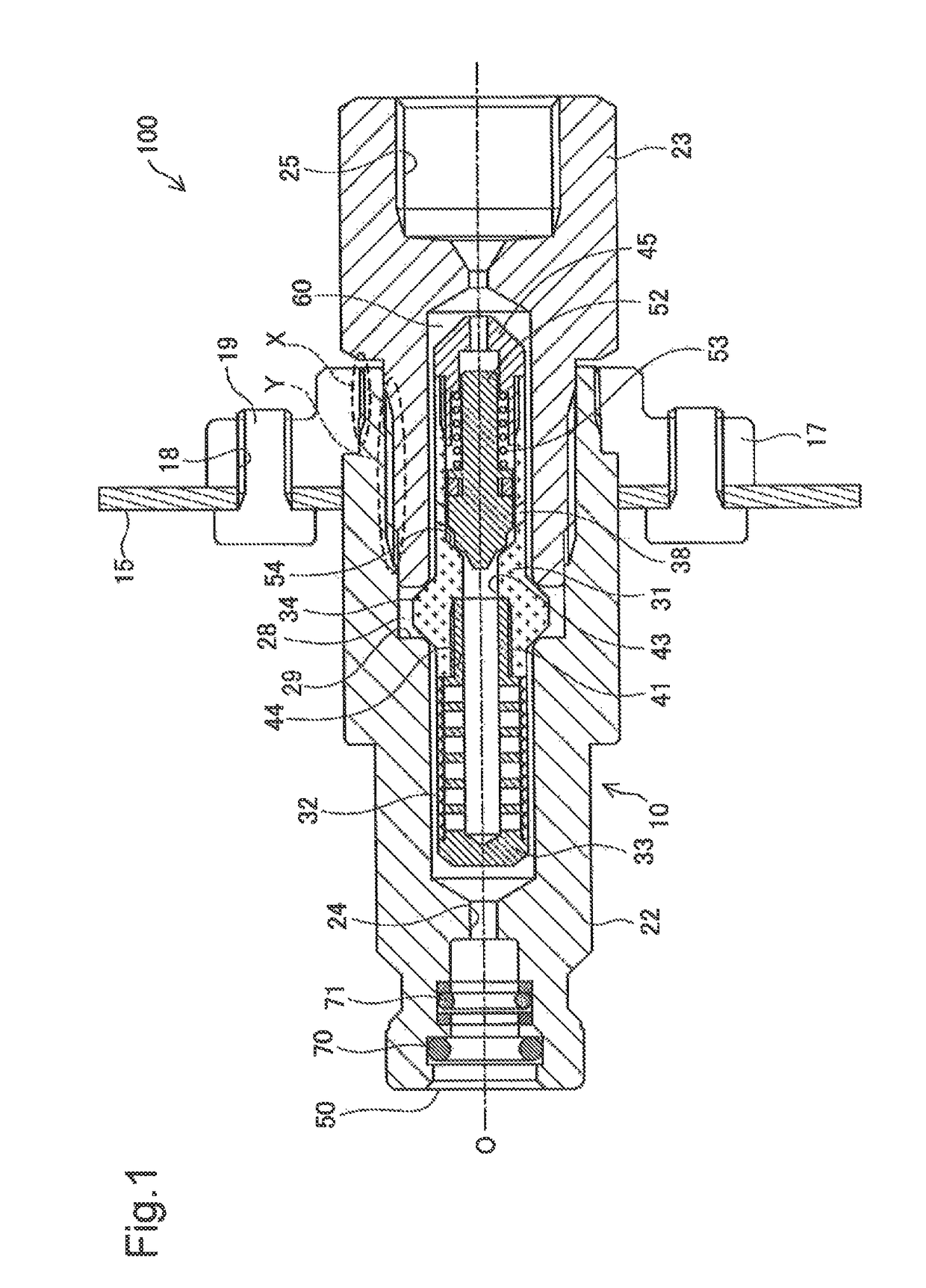
[0061]Although the casing flow path 60 formed between the casing 20 and the subassembly 30 is metal-sealed in the above embodiment described using the protruded portion 34, different structures may also be adopted. For example, the seal described above may be comprised of an O-ring or a resin seal which are provided separately from the valve housing 31.

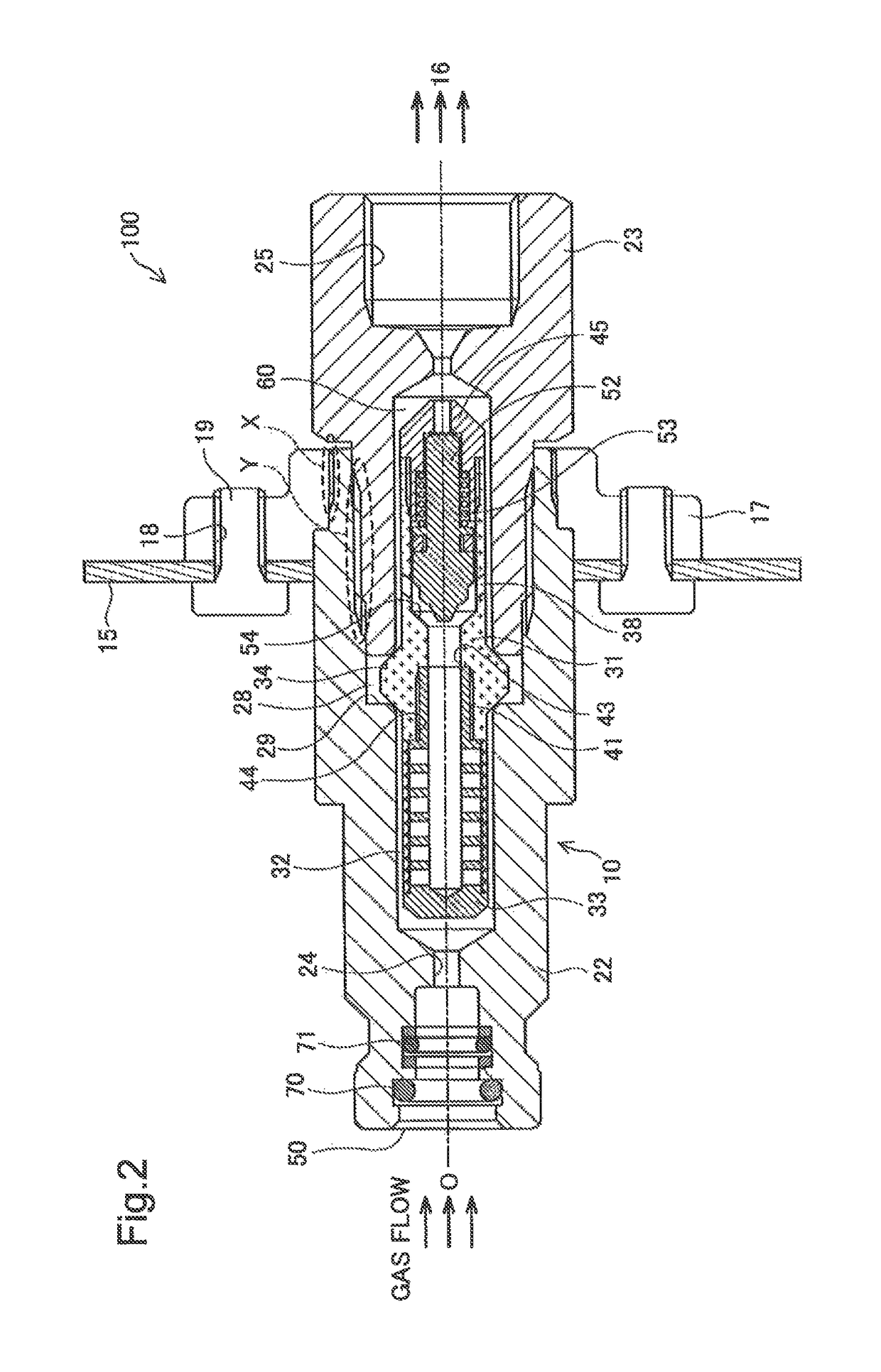
[0062]FIG. 7 is a cross-sectional view illustrating a receptacle structure 200 provided with a check valve 210 of this modification. In FIG. 7, a state where the check valve is open, similar to FIG. 2, is illustrated. In this modification, the same reference numerals are given to parts which are common to the parts of the receptacle structure 100 described in the embodiment, and detailed description thereof is thus omitted.

[0063]A protruded portion 234 is formed in an outer surface of a valve housing 231 provided to the check valve 210, instead of the protruded portion 34. The protruded portion 234 is p...

modification 2 (

Modification of Subassembly)

[0066]Although the filter 32 is compressed and held by the a filter end support portion 39 of the filter guide 33 and the tip-end supporting portion 46 of the valve housing 31 in the embodiment, different structures may also be adopted. For example an end portion of the filter 32 may be fixed to the filter guide 33 by welding, without providing at least one of the a filter end support portion 39 having the flange-shaped structure and the tip-end supporting portion 46 for holding the filter 32. By having such a structure, similar effects of reducing the hydrogen flow which bypasses the filter 32 can also be acquired. Note that, when the filter 32 is pinched and held from both sides similar to the embodiment, it is desirable because particular processes, such as welding, become unnecessary, and only the filter 32 can be replaced at the time of a maintenance, without replacing the filter guide 33. When both ends of the filter 32 in the axial direction are we...

modification 3 (

Modification of Receptacle Structure)

[0070]Although the attachment of the check valve 10 to the flange 17 is achieved by the threaded-engagement fastening in the embodiment (fastening portion X in FIGS. 1 and 2) different structures may also be adopted. For example, the check valve 10 and the flange 17 may be fixed to each other by using a snap ring, etc.

[0071]Although the flange 17 is used as the interposition member which is placed between the check valve 10 and the vehicle body (vehicle body 15) in the embodiment, different structures may also be adopted. For example, the casing 20 and the vehicle body 15 may be directly fastened to each other by using bolts and nuts as the interposition member. Also in such a case, when the interposition member is made of metal which is lower in the ionization tendency than the casing, similar effects of preventing the corrosion of the casing and improving the durability of the check valve 10 can be acquired.

[0072]In the embodiment, although the...


PUM

PropertyMeasurementUnit
thicknessaaaaaaaaaa
diameteraaaaaaaaaa
lengthaaaaaaaaaa

Abstract

In order to reduce a pressure loss in a check valve and simplify a manufacturing process, a check valve (10) configured to be disposed in piping of fluid is provided, which includes a valve housing (31) including a valve element (52) and a valve seat (54) therein, a casing (20) that is configured to place the valve housing therein, in which a casing flow path (60) is provided between the casing and the valve housing to make a flow of the fluid in an axial direction of the valve housing. In the valve housing, a communicating hole (38) and sealing portion (34) are formed. The communicating hole that is formed through the valve housing in a thickness direction thereof introduces the fluid, which flows through between the valve element and the valve seat at the open position of the check valve, into the casing flow path. The sealing portion that is provided on an outer surface of the valve housing upstream of the communicating hole in a flow direction of the fluid in the casing flow path, is configured to come into contact with an inner surface of the casing to seal the casing flow path and position the valve housing in a radial direction perpendicular to the axial direction relative to the casing.

Description

CROSS REFERENCE TO RELATED APPLICATION[0001]This application claims priority to Japanese Patent Application No. 2014-229862, filed on Nov. 12, 2014, the contents of all of which are incorporated herein by reference in their entirety.BACKGROUND OF THE INVENTIONField[0002]The present invention relates to a check valve and a receptacle structure provided with the check valve.Related Art[0003]As a check valve for preventing a back flow of Hold, JP2013-535621A proposes a check valve in which a valve element pressed in a direction opposite from an original flow direction of fluid (closing direction), and a valve element supporting part which surrounds and supports the valve element so as to extend in axial direction of the valve element (moving direction of the valve element) are provided inside a casing, and a flow path through which the fluid flows in the axial direction described above is formed between the valve element supporting part and the casing. The structure in which the flow p...

Claims


Application Information

Patent Timeline
Patent Type & Authority Patents(United States)
IPC IPC(8): F17C13/04F16K27/02F16K15/06
CPCF16K27/0209F16K15/063F17C13/04Y10T137/7934F17C2221/012Y10T137/794F17C2205/0335B01D35/04Y02E60/32
Inventor ONISHI, HIROFUMIKONDO, MASAAKIYAMASHITA, AKIRANISHIO, TAKUYA
Owner TOYOTA JIDOSHA KK
Why Eureka
Try Eureka