
Micromixer of turbine system

Active Publication Date: 2013-07-25
GENERAL ELECTRIC CO
View PDF6 Cites 16 Cited by
  • Summary
  • Abstract
  • Description
  • Claims
  • Application Information

AI Technical Summary

Benefits of technology

This patent is about a micromixer in a turbine system that helps to mix and disperse air and fuel for combustion. The micromixer has a non-uniform inlet arrangement with multiple pipes that extend to an axial location. The micromixer is placed near the head end of the combustor and includes a plurality of pipes that each have an inlet and an outlet. The inlets extend through a transverse plane that is perpendicular to the longitudinal axis of the pipes. This design helps to achieve uniform mixing of air and fuel, leading to improved efficiency and performance of the turbine system.

Problems solved by technology

Due to upstream conditions, such as the flow experiencing a sharp turn just prior to entering the inlets, non-uniform mass flow often prevails, thereby hindering overall system performance.

Method used


Image

  • Micromixer of turbine system
  • Micromixer of turbine system
  • Micromixer of turbine system

Examples


Embodiment Construction

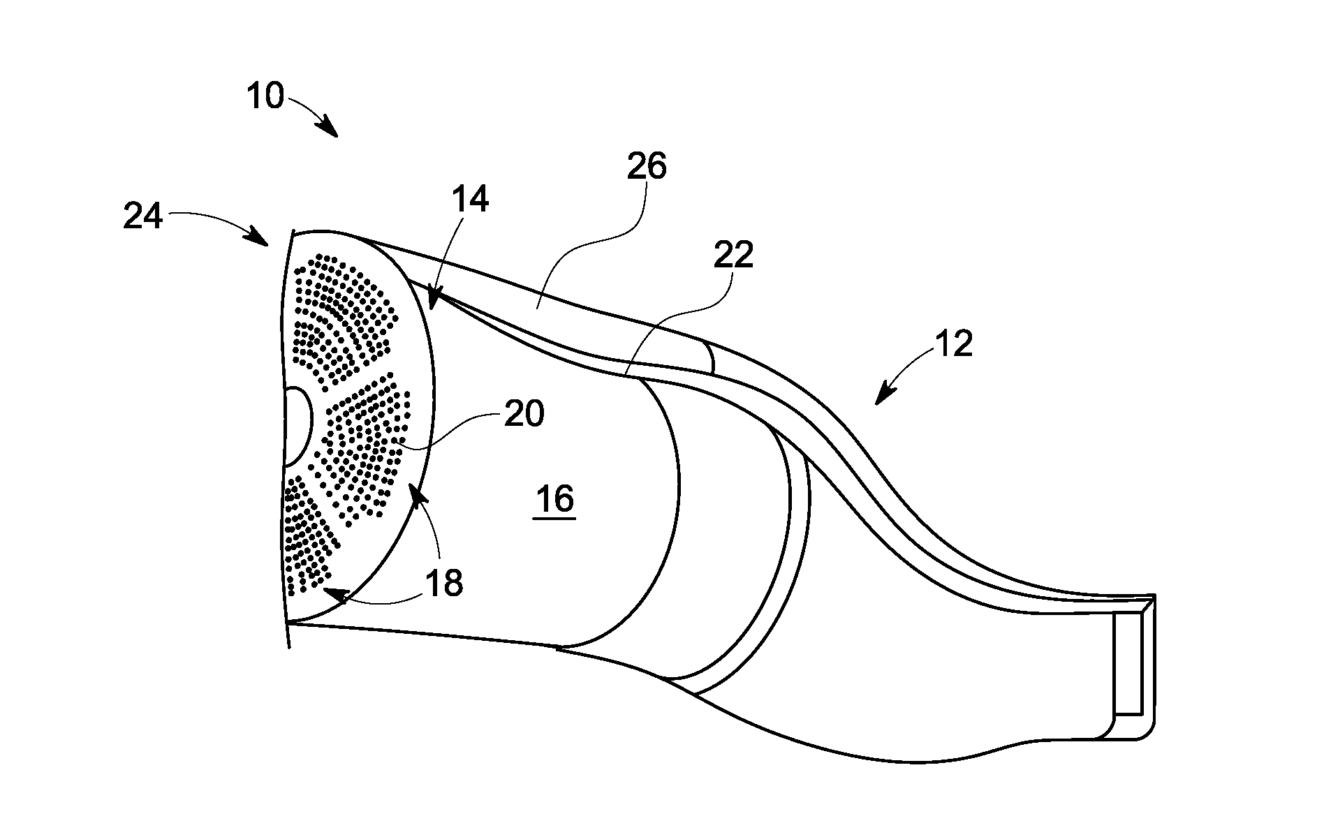
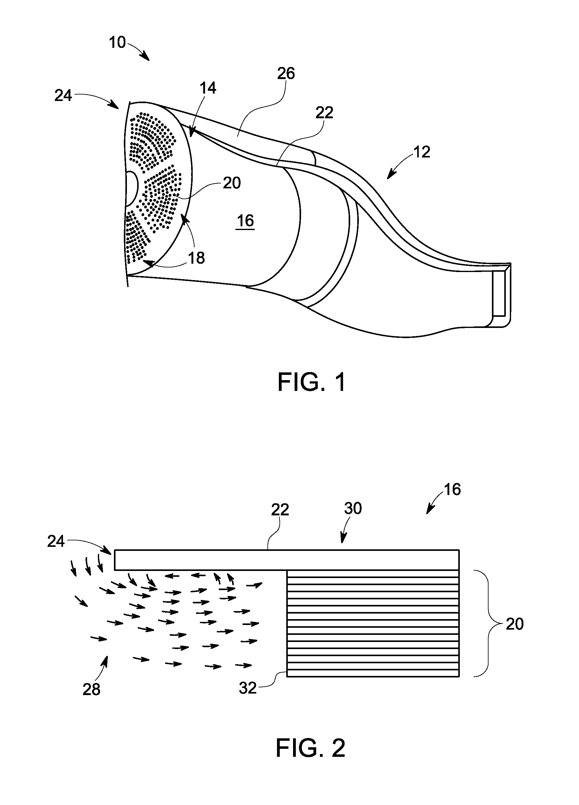
[0016]Referring to FIG. 1, illustrated is a turbine system 10 having a combustor section 12 and a head end 14. The head end 14 is disposed at an adjacent upstream location of the combustor section 12 and includes a micromixer 16. The micromixer 16 includes a plurality of sectors 18 that each comprise a plurality of pipes 20. The combustor section 12 is defined by an outer liner 22 that extends to an upstream end 24. Spaced radially outwardly of the outer liner 22, and surroundingly enclosing the outer liner 22, is a flow sleeve 26. A flow 28 of air passes upstream within an air passage 30 defined by the outer liner 22 and the flow sleeve 26 to the upstream end 24 of the outer liner 22.

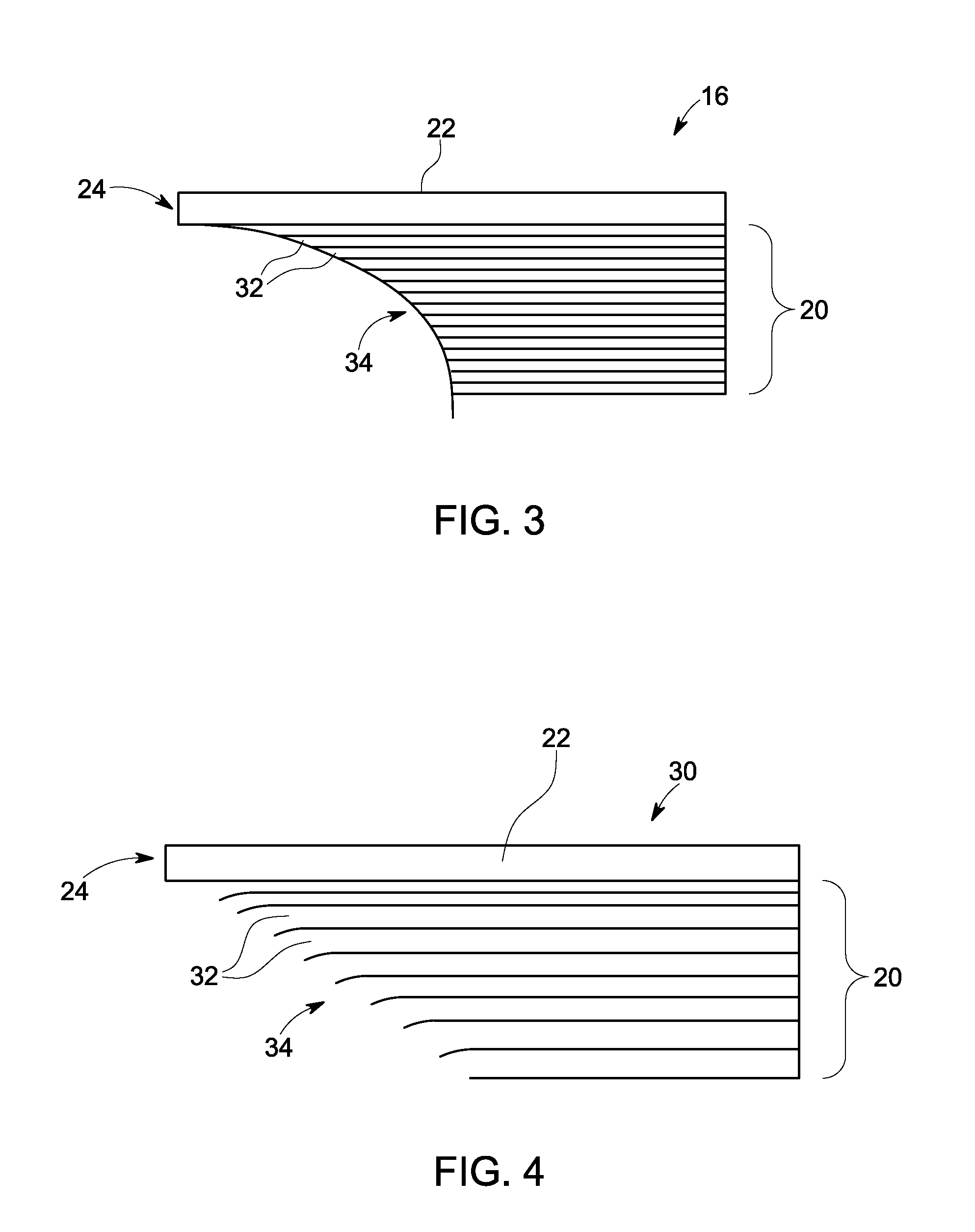
[0017]Referring to FIG. 2, upon reaching the upstream end 24 of the outer liner 22, the flow 28 makes an abrupt turn just prior to entering the micromixer 16. The plurality of pipes 20 each include an inlet 32 for receiving the flow 28. It is apparent that pipes disposed at an outer region of the plura...


PUM


Abstract

A micromixer of a turbine system is provided and the micromixer includes a plurality of pipes each having an inlet and an outlet for receiving flow and dispersing the flow to a combustor. Also provided is a non-uniform inlet arrangement defined by the inlets of the plurality of pipes, wherein at least one of the inlets extends to an axial location distinct from at least one other inlet.

Description

BACKGROUND OF THE INVENTION[0001]The subject matter disclosed herein relates to turbine systems, and more particularly to a micromixer.[0002]Turbine systems may include a micromixer, where air distribution to an individual air-fuel pipe should remain at a mean average value of the overall flow. The micromixer typically includes a plurality of pipes or tubes, each having an inlet, where the plurality of inlets are all located in a single, defined axial plane. Due to upstream conditions, such as the flow experiencing a sharp turn just prior to entering the inlets, non-uniform mass flow often prevails, thereby hindering overall system performance.BRIEF DESCRIPTION OF THE INVENTION[0003]According to one aspect of the invention, a micromixer of a turbine system includes a plurality of pipes each having an inlet and an outlet for receiving flow and dispersing the flow to a combustor. Also provided is a non-uniform inlet arrangement defined by the inlets of the plurality of pipes, wherein ...

Claims


Application Information

Patent Timeline
IPC IPC(8): F23R3/32
CPCF23R3/045F23R3/54F23R3/16
Inventor BATHINA, MAHESHNADKARNI, VAIBHAVSINGH, ARJUN
Owner GENERAL ELECTRIC CO
Learn More