Fuel nozzel

Inactive Publication Date: 2013-07-25
GENERAL ELECTRIC CO
View PDF41 Cites 4 Cited by
  • Summary
  • Abstract
  • Description
  • Claims
  • Application Information

AI Technical Summary

Benefits of technology

The patent text describes a fuel nozzle that mixes a flow of fuel and air for combustion in a gas turbine engine. The nozzle includes a collar with air vanes and purge holes for a flow of purge air. The purge air helps to limit the creation of recirculation zones downstream of the nozzle, which can improve engine efficiency. The technical effects of this design include improved engine performance and efficiency through reduced recirculation zones.

Problems solved by technology

Flame holding may cause significant damage to the fuel nozzles and / or reduce the performance of the fuel nozzles and the overall gas turbine engine.
Such a flammable mixture potentially may result in flame holding inside the fuel nozzles.
Flame holding inside fuel nozzles may result in the fuel nozzles burning out, i.e., experiencing flame damage therein.

Method used


Image

  • Fuel nozzel
  • Fuel nozzel
  • Fuel nozzel

Examples


Embodiment Construction

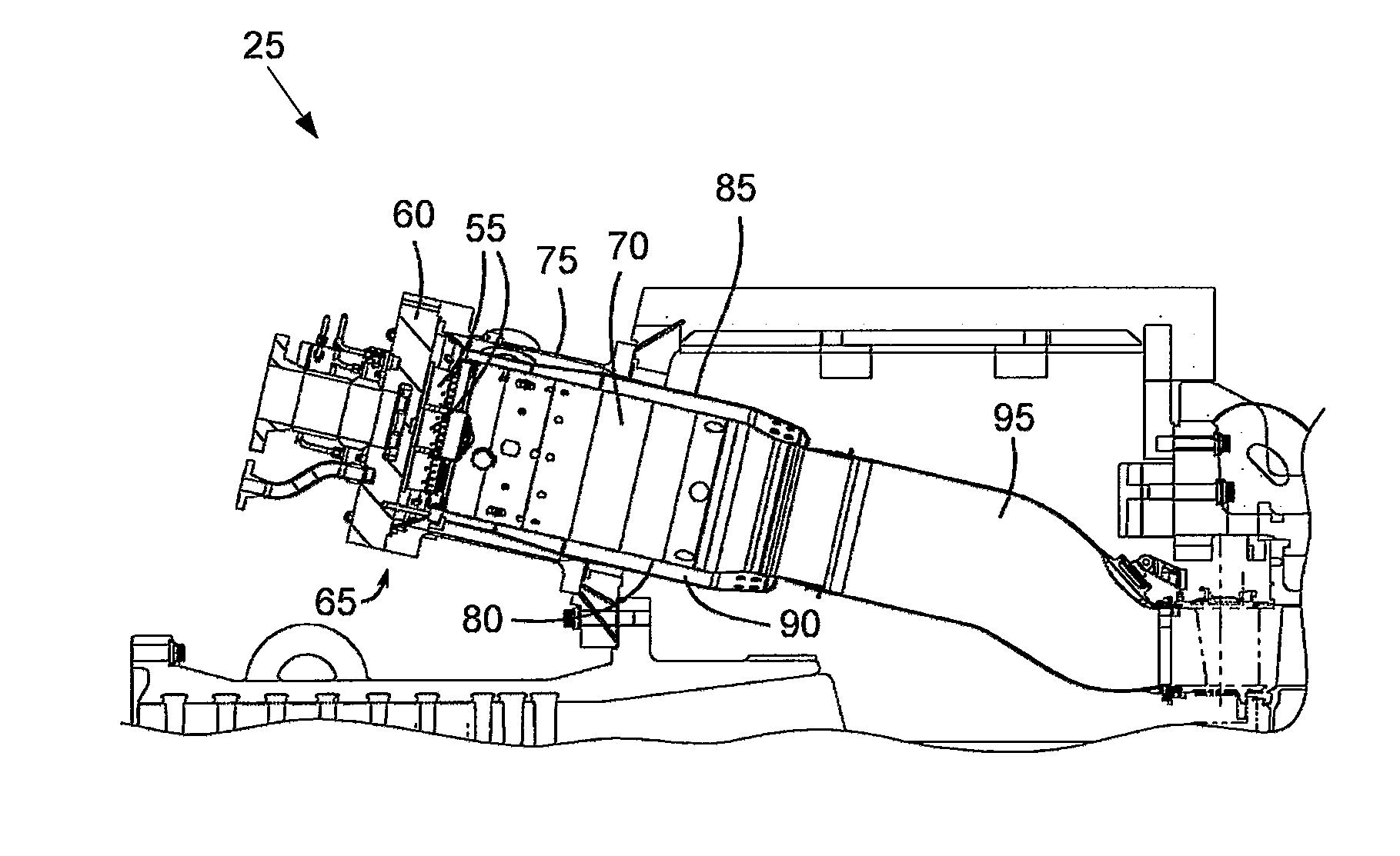
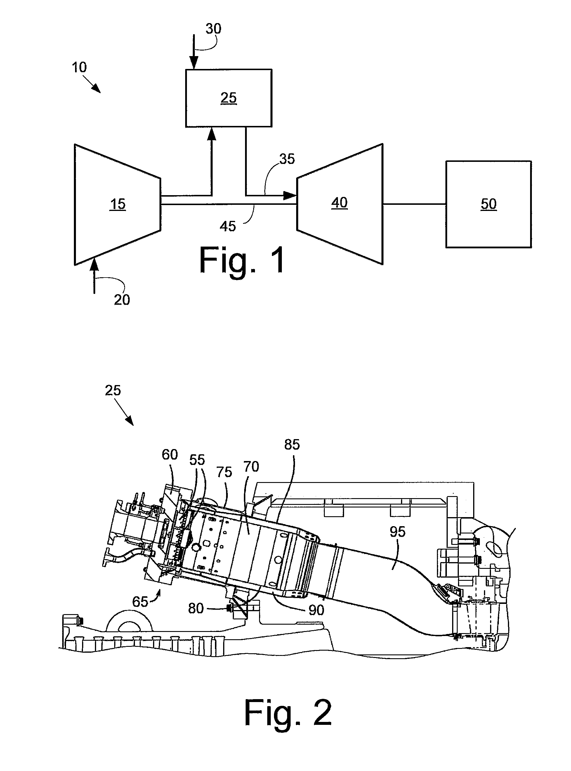
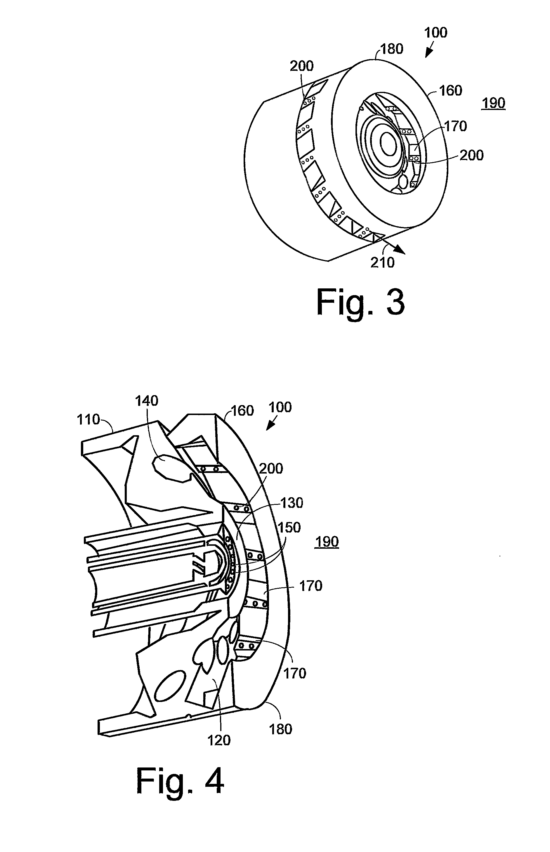
[0013]Referring now to the drawings, in which like numerals refer to like elements throughout the several views, FIG. 1 shows a schematic view of gas turbine engine 10 as may be used herein. The gas turbine engine 10 may include a compressor 15. The compressor 15 compresses an incoming flow of air 20. The compressor 15 delivers the compressed flow of air 20 to a combustor 25. The combustor 25 mixes the compressed flow of air 20 with a pressurized flow of fuel 30 and ignites the mixture to create a flow of combustion gases 35. Although only a single combustor 25 is shown, the gas turbine engine 10 may include any number of combustors 25. The flow of combustion gases 35 is in turn delivered to a turbine 40. The flow of combustion gases 35 drives the turbine 40 so as to produce mechanical work. The mechanical work produced in the turbine 40 drives the compressor 15 via a shaft 45 and an external load 50 such as an electrical generator and the like. Other configurations and other compon...


PUM


Abstract

The present application provides a fuel nozzle for mixing a flow of fuel and a flow of air. The fuel nozzle may include a downstream face, a number of fuel passages positioned about the downstream face for the flow of fuel, and a nozzle collar position about the downstream face. The nozzle collar may include a number of air vanes for the flow of air and one or more purge holes therethrough.

Description

TECHNICAL FIELD[0001]The present application and the resultant patent relate generally to a gas turbine engine and more particularly relate to a fuel nozzle with a nozzle collar having a number of purge holes therein for improved fuel-air mixing, flame holding resistance, and overall performance.BACKGROUND OF THE INVENTION[0002]Generally described, a gas turbine engine may employ one or more fuel nozzles to facilitate fuel-air mixing in a combustor. Each fuel nozzle may direct a flow of fuel, a flow of air, and optional flows of other fluids into the combustor for combustion therein. In certain conditions, a combustion flame may flash back and / or hold to a surface of the fuel nozzle. Flame holding may cause significant damage to the fuel nozzles and / or reduce the performance of the fuel nozzles and the overall gas turbine engine.[0003]Specifically, flame holding may occur if a flammable fuel-air mixture resides in a low velocity region in close proximity to a combustion source. In f...

Claims


Application Information

Patent Timeline
IPC IPC(8): F23D14/62
CPCF23R3/14F23D11/386F23D11/383F23R3/28
Inventor MENON, ARVIND VENUGOPALSLOBODYANSKIY, ILYA ALEKSANDROVICHBARUAH, ABINASH
Owner GENERAL ELECTRIC CO
Why Eureka
Try Eureka