Metal mesh on ceramic bracket; ceramic bracket with metal insert; metal bracket with tooth-colored coating; self-legating, low profile, metal bracket; and methods of making same

a technology of ceramic brackets and metal meshes, applied in the field of metal meshes on ceramic brackets, can solve the problems of inability to achieve the same degree of tooth alignment, the braces may have to be replaced, and the alignment of the teeth is not typically the same degree, so as to achieve less alignment with clear braces

Inactive Publication Date: 2013-08-01
EICHELBERGER JOHN E +2
View PDF0 Cites 14 Cited by
  • Summary
  • Abstract
  • Description
  • Claims
  • Application Information

AI Technical Summary

Benefits of technology

[0014]Another aspect of the invention provides a self-legating orthodontic bracket and alignment system. The system includes a bracket portion including a receiving slot. The receiving slot includes first and second open ends. The slot extends across at least a portion of the bracket portion and receives an arch wire. The receiving slot is bounded by at least one snap member that defines a first portion and a second portion of the receiving slot. The first portion has a width smaller than a width of the second portion. In other words, the receiving slot is narrow in one part and wide in one part. Optionally, an aligner clip couples to an outer surface of the bracket portion and slides along the bracket portion and provides a visual indication of an alignment direction of the bracke

Problems solved by technology

As orthodontic treatment with braces may occur over a period of one to several years, the brackets may have to be replaced due to breakage or due to a change in the size or style of the wire used in the braces.
However, such braces typically do not achieve alignment of the teeth to the same degree as braces installed on the fronts of teeth.
However, as with braces installed behind the teeth, less alignment ca

Method used


Image

  • Metal mesh on ceramic bracket; ceramic bracket with metal insert; metal bracket with tooth-colored coating; self-legating, low profile, metal bracket; and methods of making same
  • Metal mesh on ceramic bracket; ceramic bracket with metal insert; metal bracket with tooth-colored coating; self-legating, low profile, metal bracket; and methods of making same
  • Metal mesh on ceramic bracket; ceramic bracket with metal insert; metal bracket with tooth-colored coating; self-legating, low profile, metal bracket; and methods of making same

Examples


Embodiment Construction

[0047]Referring now to the drawings, wherein like reference numerals designate identical or corresponding parts throughout the several views.

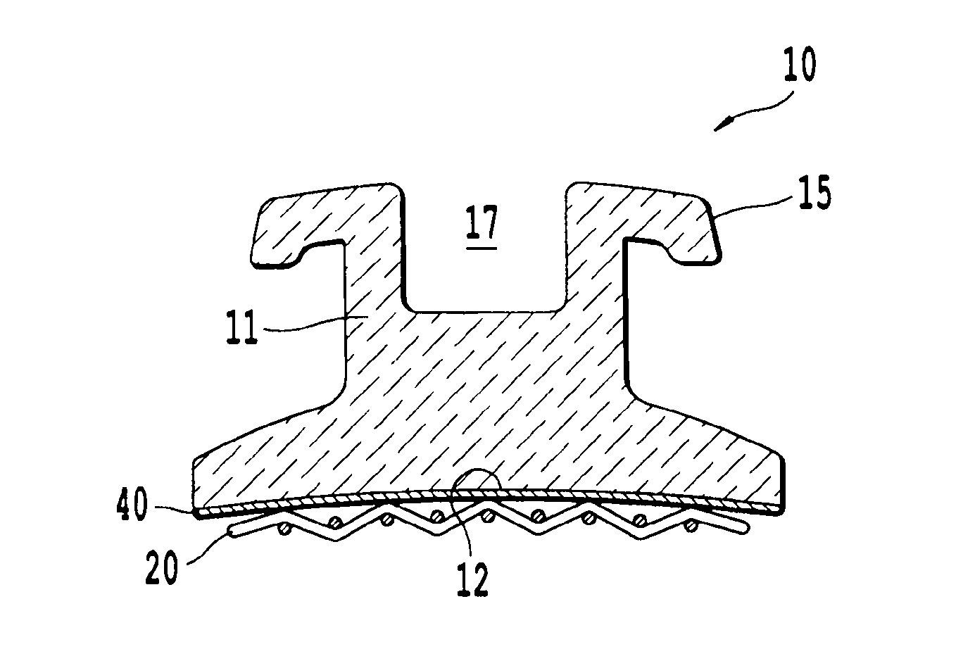
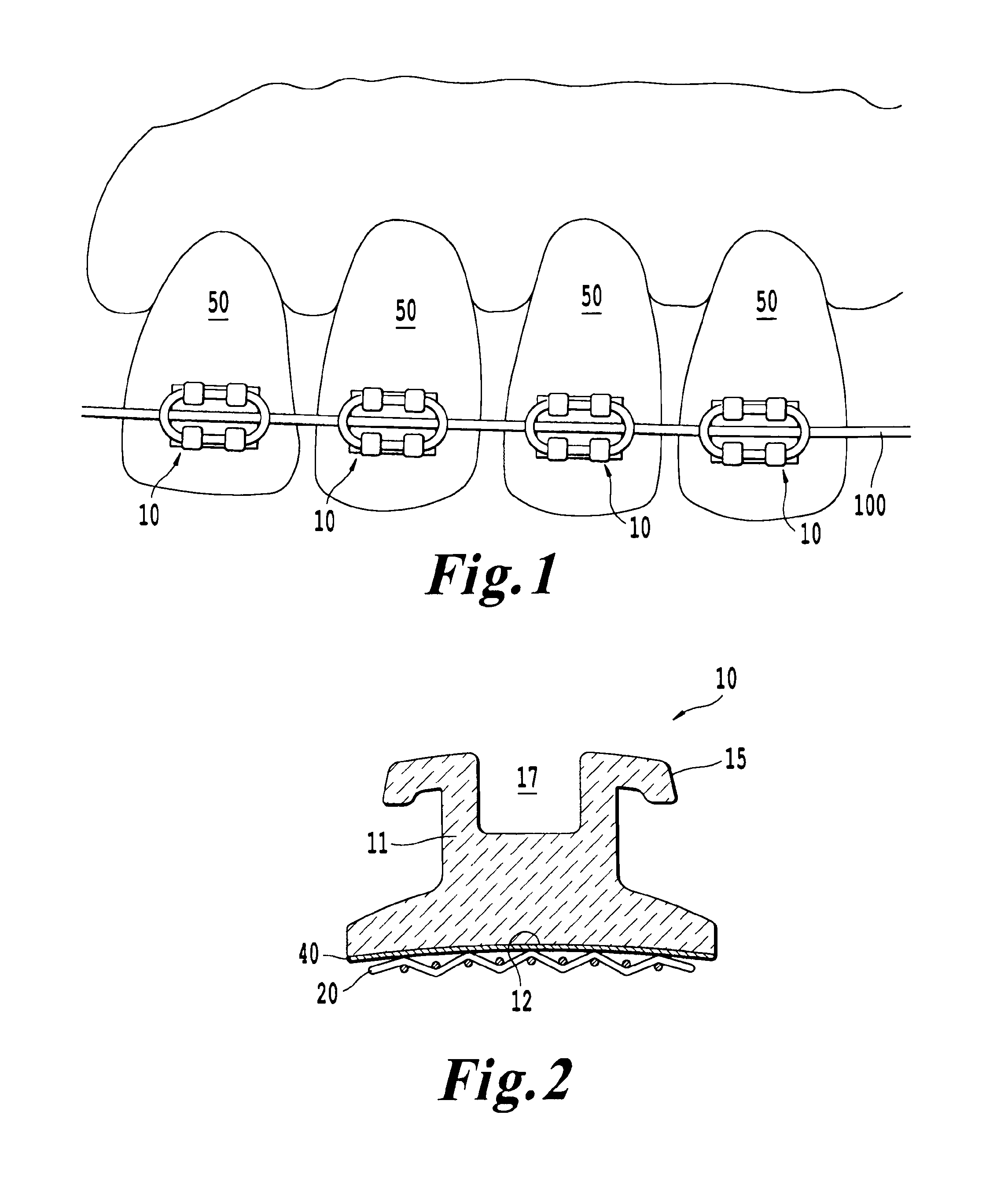
[0048]With reference to FIG. 2, a bracket 10 according to one example of the present invention is shown in side view. The bracket 10 is made of dental-grade ceramic and a metal mesh bonded at the bottom of the brace which is to be bonded to the tooth during the brace installation. With reference to FIG. 1, a plurality of the brackets 10 may be attached to a plurality of teeth in a patient's mouth. Aside from the configuration depicted in FIG. 1, various arrangements of the brackets 10 are possible.

[0049]The bracket 10 shown in FIG. 2 includes a receiving slot, in this case wire holder 17, which is configured to receive one or more types of arch wire such as round arch wire 100 or polygonal arch wire such as square arch wire 101 (see FIGS. 8B and 8C). Typically, the orthodontist will insert the arch wire 100 / 101 with a predetermined amount of to...


PUM


Abstract

An orthodontic bracket includes a bracket portion including a receiving slot extending across at least a portion of the bracket portion and configured to receive an arch wire. The bracket includes a metal mesh bonded to the ceramic bracket portion on a side of the ceramic bracket portion opposite the receiving slot. Another orthodontic bracket includes a metal core coated with a tooth-colored coating. Methods of attaching and aligning the brackets are provided as well as a tool for aligning the brackets. Inserts are also described for reinforcing the brackets and/or increasing a surface area for enhancing bonding strength.

Description

BACKGROUND OF THE INVENTION[0001]1. Field of the Invention[0002]This invention relates to a bracket configured to support arch wires used in braces for teeth. Another example of the invention relates to a ceramic bracket for braces for teeth, wherein the ceramic bracket includes a metal insert. Another example of the invention includes a metal bracket for braces installed on a patient's teeth, wherein the metal bracket includes a tooth-colored coating. Another example of the invention relates to a self-legating, low-profile, metal bracket used to support arch wires for braces installed on patient's teeth.[0003]2. Description of the Related Art[0004]Orthodontic therapy relates to the treatment of improperly aligned teeth via mechanical straightening of the teeth over time. Typically, orthodontic treatment involves use of a mouth-piece or use of “braces” to apply pressure to teeth over a long period of time to gradually force the teeth into alignment.[0005]Treatment with braces typica...

Claims


Application Information

Patent Timeline
IPC IPC(8): A61C7/30
CPCA61C7/146A61C7/148A61C7/30A61C7/28A61C7/16
Inventor EICHELBERGER, JOHN E.RHEE, HYOP SEUNGGIPE, CHRIS
Owner EICHELBERGER JOHN E
Why Eureka
Try Eureka