Lighting device with a waveguide plate

a technology of waveguide plate and light source, which is applied in the direction of planar/plate-like light source, lighting and heating apparatus, instruments, etc., can solve the problems of inefficiency, difficult to couple light from side surfaces into the waveguide, and insufficient surface area on the edges of the waveguide, etc., to facilitate a large number of total internal reflections

Active Publication Date: 2013-08-22
KONINKLIJKE PHILIPS ELECTRONICS NV
View PDF2 Cites 16 Cited by
  • Summary
  • Abstract
  • Description
  • Claims
  • Application Information

AI Technical Summary

Benefits of technology

[0052]This reflective element will in general be a diffuse reflective element. Further reflectiv

Problems solved by technology

However, coupling light into thin waveguides is rather difficult and may be inefficient.
When light is to be coupled from a side surface the thickness of the LED should be considerably smaller than the thickness of the waveguide making it difficult to couple light from side surfaces into t

Method used


Image

  • Lighting device with a waveguide plate
  • Lighting device with a waveguide plate
  • Lighting device with a waveguide plate

Examples


Embodiment Construction

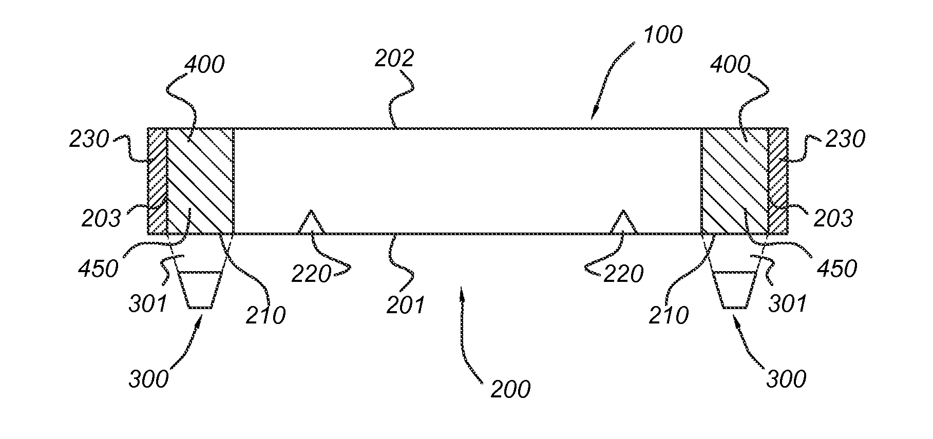
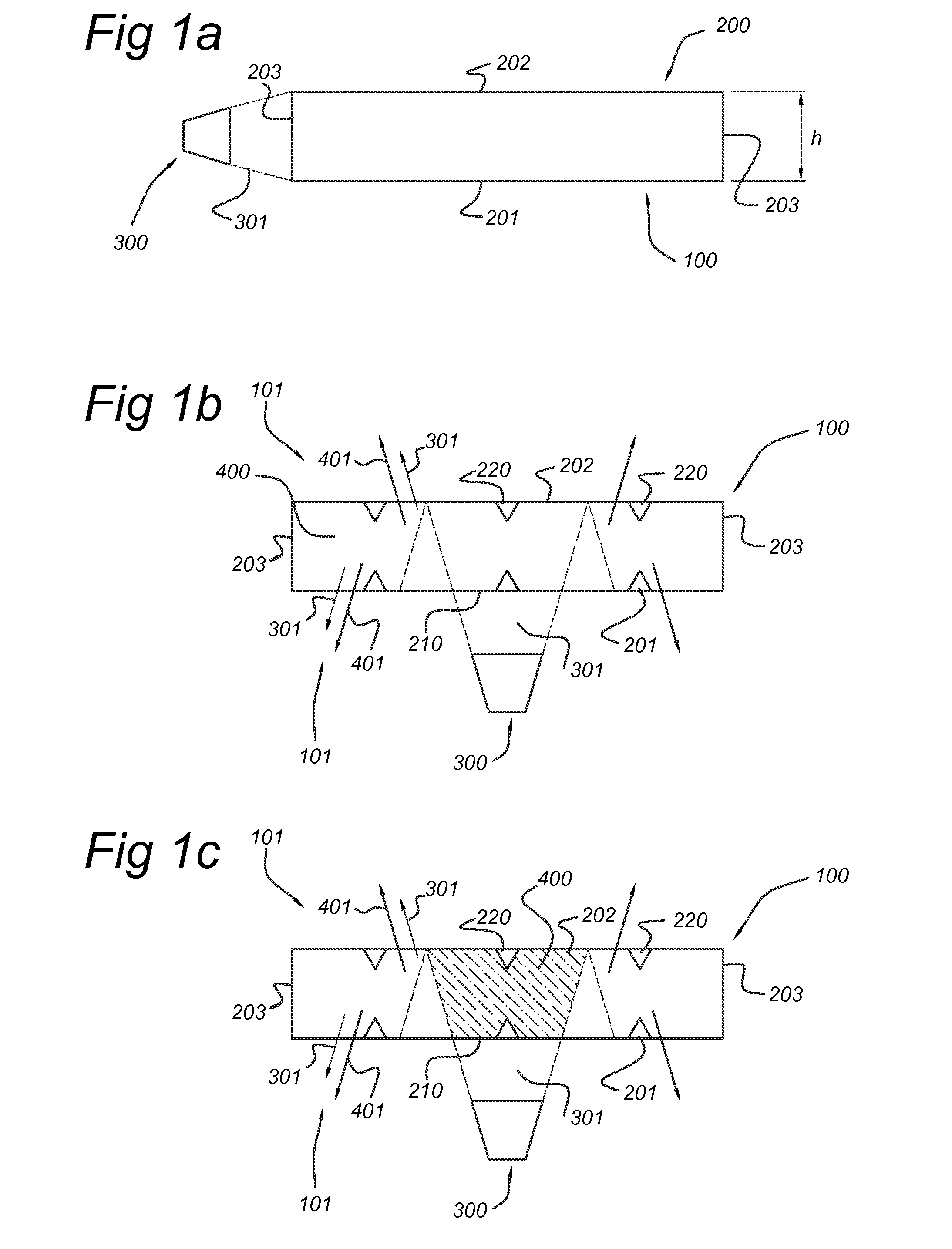
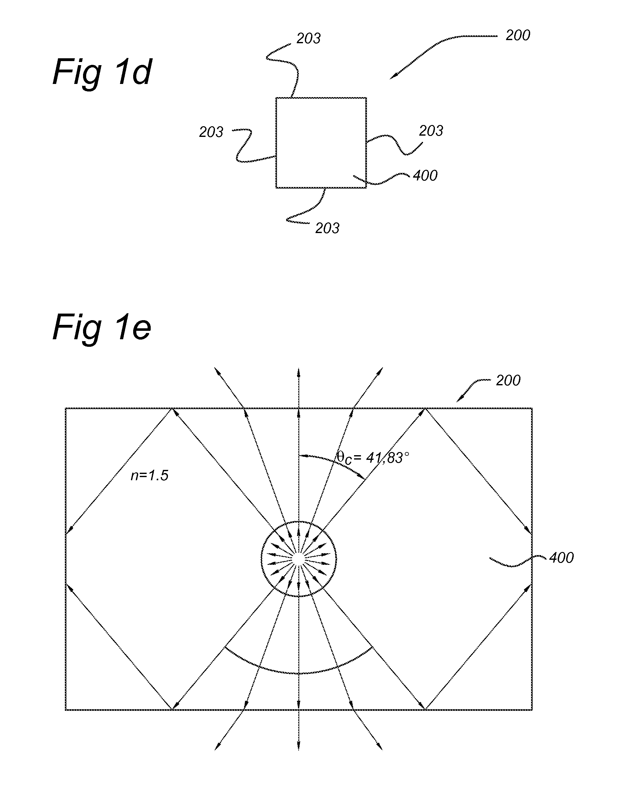
[0067]FIG. 1a schematically depicts a lighting device 1 comprising a waveguide 200 having a first surface 201, a second surface 202 and an edge surface 203. The waveguide 200 is a plate, here planar, having a height h. The lighting device 1 further comprises a light source 300, which provides light to the edge surface 203 for coupling light source light 301 of the light source 300 into the waveguide 200.

[0068]The thinner the waveguide 200, i.e. with decreasing h, light incoupling may become difficult. Hence, the invention suggests providing light via another incoupling surface, especially in a direction perpendicular to one or more of the first surface 201 and the second surface 202, as shown in the drawings that follow.

[0069]The embodiments of the invention schematically depicted below are depicted with constant h. In general, h will be constant over the waveguide plate 200, but in a specific embodiment, h may also vary.

[0070]FIG. 1b schematically depicts an embodiment of lighting ...


PUM


Abstract

The invention provides a lighting device comprising (a) a transparent waveguide plate (200), with first surface (201), opposite second surface (202), and edge surface between the first surface and the second surface, (b) a light source (300) for providing light source light towards a light incoupling surface of the transparent waveguide plate, configured to provide at least part of the light source light in a direction perpendicular to one or more of the first surface and the second surface. The transparent waveguide plate further comprises a luminescent material, (400) configured to convert at least part of the light source light into luminescent material emission, and light outcoupling means (220) for coupling luminescent material emission and optionally light source light out of the transparent waveguide plate as lighting device light in a direction away from one or more of the first surface and the second surface.

Description

FIELD OF THE INVENTION[0001]The invention relates to a lighting device comprising a waveguide plate.BACKGROUND OF THE INVENTION[0002]Lighting systems wherein light transmitting plates are used are known in the art. US2010020531, for instance, describes a back lighting unit in which lower and upper surfaces of a light transmitting plate function as incident and exit surfaces of light, respectively, and a luminescent material film structure for wavelength-converting the light is provided at a position which the light is incident on or exits from said plate. The in US2010020531 described back lighting unit includes a light emitting means including a light emitting diode disposed to emit light upwards, a light transmitting plate disposed over the light emitting diode, having a lower surface allowing light to be incident thereon and an upper surface allowing light to exit therefrom, and a luminescent material film structure including a particulate luminescent material, formed on at least...

Claims


Application Information

Patent Timeline
IPC IPC(8): F21V8/00
CPCG02B6/0003G02B6/0015G02B6/0023G02B6/005Y10S977/95G02B6/0033Y10S977/773Y10S977/774B82Y20/00
Inventor HIKMET, RIFAT ATA MUSTAFAVERBEEK, ROY GERARDUS FRANCISCUS ANTONIUVAN BOMMEL, TIES
Owner KONINKLIJKE PHILIPS ELECTRONICS NV
Why Eureka
Try Eureka