Coherent light receiving device, system, and method

a light receiving device and coherent technology, applied in the field of coherent light receiving devices, systems and methods, can solve the problems of varying signal timing of the photodetector output, and achieve the effect of reducing timing deviation

Inactive Publication Date: 2013-08-22
NEC CORP
View PDF6 Cites 16 Cited by
  • Summary
  • Abstract
  • Description
  • Claims
  • Application Information

AI Technical Summary

Benefits of technology

[0045]According to the invention, it is possible to compensate for or to considerably reduce timing deviation which becomes problematic when an optical signal influenced by wavelength dispersion is received by intradyne detection.

Problems solved by technology

In the coherent light receiving scheme of the intradyne detection, there is a problem in that, when an optical signal influenced by wavelength dispersion is received, the signal timing of the photodetector output varies due to variation in wavelength dispersion influenced on the optical signal and variation in the frequency difference between the optical signal and local light.

Method used


Image

  • Coherent light receiving device, system, and method
  • Coherent light receiving device, system, and method
  • Coherent light receiving device, system, and method

Examples


first embodiment

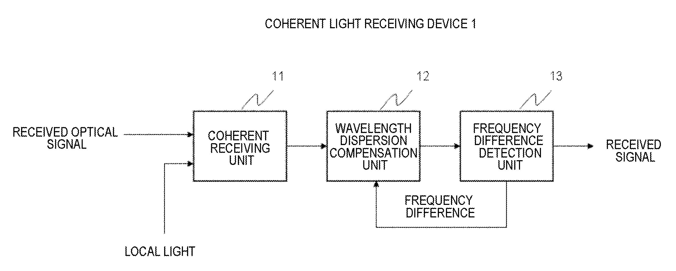
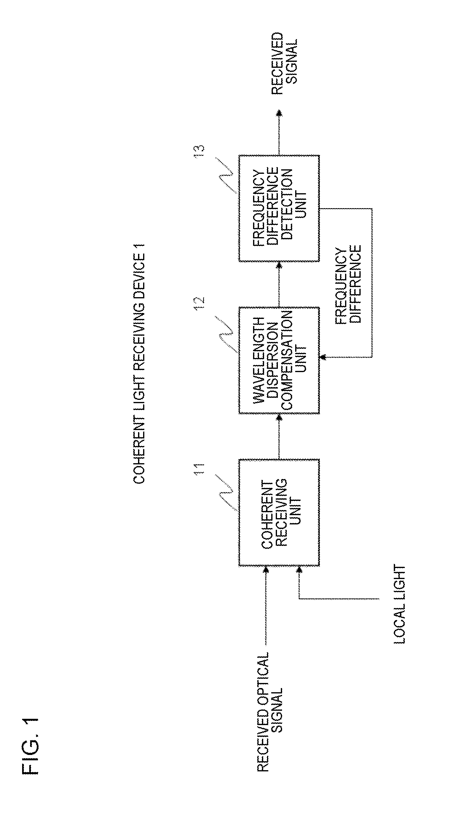
[0061]FIG. 1 is a block diagram illustrating the configuration of a coherent light receiving device according to the invention.

[0062]It should be noted that embodiments are for illustration, and the device and system of the disclosure are not limited to the configuration of the following embodiments.

[0063]The coherent light receiving device 1 includes a coherent receiving unit 11, a wavelength dispersion compensation unit 12, and a frequency difference detection unit 13.

[0064]The coherent light receiving device 1 receives an optical signal including waveform distortion due to wavelength dispersion, mixes the optical signal with local light, performs optical coherent detection to convert the optical signal to an electrical signal, converts the converted electrical signal to a digital signal, and outputs the digital signal.

[0065]The wavelength dispersion compensation unit 12 compensates for waveform distortion in the digital signal output from the coherent receiving unit 11, and outpu...

second embodiment

[0078]Next, a coherent light receiving device according to the invention will be described.

[0079]FIG. 4 is a block diagram illustrating the configuration of a coherent light receiving device according to a second embodiment of the invention. A coherent light receiving device 2 of the second embodiment includes a coherent receiving circuit 21, a local light source 22, a wavelength dispersion compensation circuit 23, a wavelength dispersion compensation factor calculation circuit 24, and a received signal demodulation unit 25.

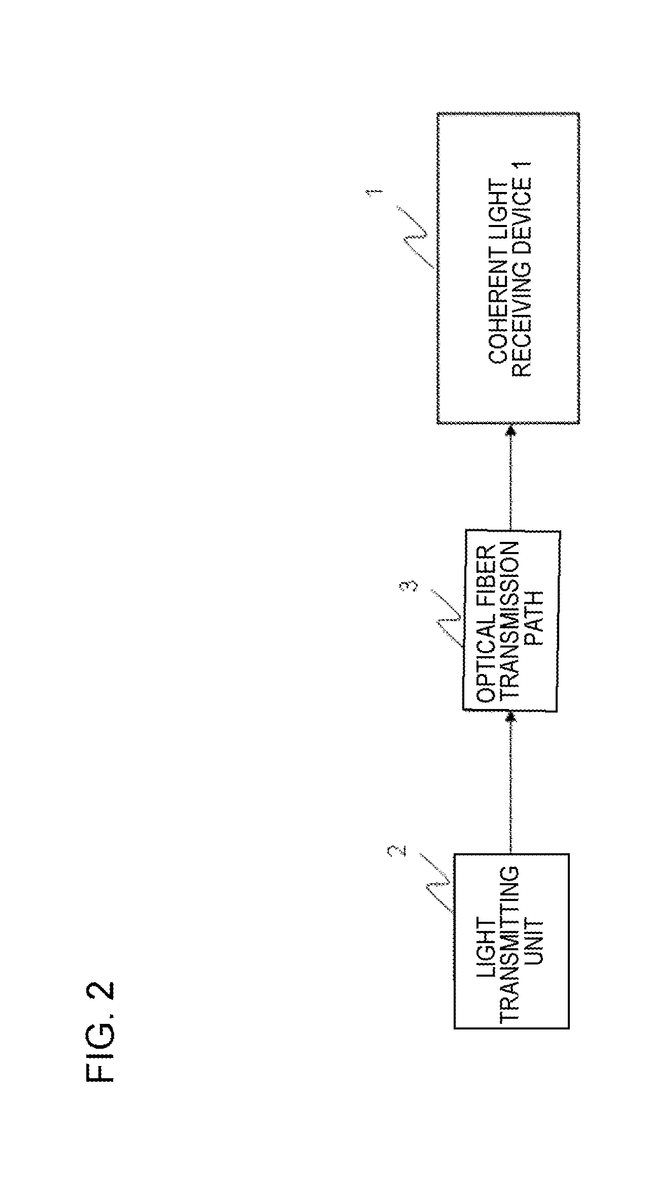
[0080]In FIG. 4, the coherent receiving circuit 21 receives a phase-modulated optical signal from a light transmitting unit (not shown) (for example, the light transmitting unit 2 of FIG. 2) through an optical fiber transmission path (not shown) (for example, the optical fiber transmission path 3 of FIG. 2). The modulation scheme of the optical signal is not limited to phase modulation, and any modulation scheme may be used insofar as coherent light reception is ...

third embodiment

[0132]Next, a coherent light receiving device of a third embodiment will be described.

[0133]FIG. 7 is a block diagram illustrating the configuration of a coherent light receiving device according to a third embodiment of the invention. A coherent light receiving device 3 of the third embodiment includes a coherent receiving circuit 31, a local light source 32, a wavelength dispersion compensation circuit 33, a wavelength dispersion compensation factor calculation circuit 34, a received signal demodulation circuit 35, and a factor shift circuit 36.

[0134]In FIG. 7, the coherent receiving circuit 31 receives a phase-modulated optical signal from a light transmitting unit (not shown) (for example, the light transmitting unit 2 of FIG. 2) through an optical fiber transmission path (not shown) (for example, the optical fiber transmission path 3 of FIG. 2). The modulation scheme of the optical signal is not limited to phase modulation, and any modulation scheme may be used insofar as coher...


PUM


Abstract

A coherent light receiving device includes a coherent receiving unit which mixes a received optical signal with local light and performs optical coherent detection to output a digital signal, a wavelength dispersion compensation unit which compensates for waveform distortion in the digital signal and outputs a digital signal after compensation, and a frequency difference detection unit which detects the frequency difference between the received optical signal and local light and notifies the wavelength dispersion compensation unit of the frequency difference, wherein the wavelength dispersion compensation unit performs compensation using a transfer function which is based on the frequency difference notified from the frequency difference detection unit and represents waveform distortion due to wavelength dispersion.

Description

TECHNICAL FIELD[0001]The present invention relates to a coherent light receiving device, system, and method, and in particular, a coherent light receiving device, system, and method in which an intradyne coherent detection technique and a digital signal processing technique are combined together.BACKGROUND ART[0002]An optical fiber communication system is an important technique which realizes long-distance and large-volume communication. In recent years, as a technique for realizing large-volume optical fiber communication, a technique which performs signal equalization and demodulation by a coherent optical communication scheme and digital signal processing has been studied and developed.[0003]In the coherent optical communication scheme, information to be transmitted is applied to one or both of the amplitude and phase of light waves and then transmitted. In order to receive information applied to the amplitude or phase, received light is mixed with local oscillation light (in the...

Claims


Application Information

Patent Timeline
Patent Type & Authority Applications(United States)
IPC IPC(8): H04B10/61
CPCH04B10/6161H04B10/6163H04B10/6165
Inventor FUKUCHI, KIYOSHI
Owner NEC CORP
Why Eureka
Try Eureka