Traffic portal enquiry and alert system

a technology of traffic portals and alert systems, applied in the field of trip time computation, can solve problems such as many limitations and drawbacks of current systems

Inactive Publication Date: 2013-08-22
APPY RISK TECH LTD
View PDF17 Cites 118 Cited by
  • Summary
  • Abstract
  • Description
  • Claims
  • Application Information

AI Technical Summary

Problems solved by technology

There are many limitations and d

Method used


Image

  • Traffic portal enquiry and alert system
  • Traffic portal enquiry and alert system
  • Traffic portal enquiry and alert system

Examples


Embodiment Construction

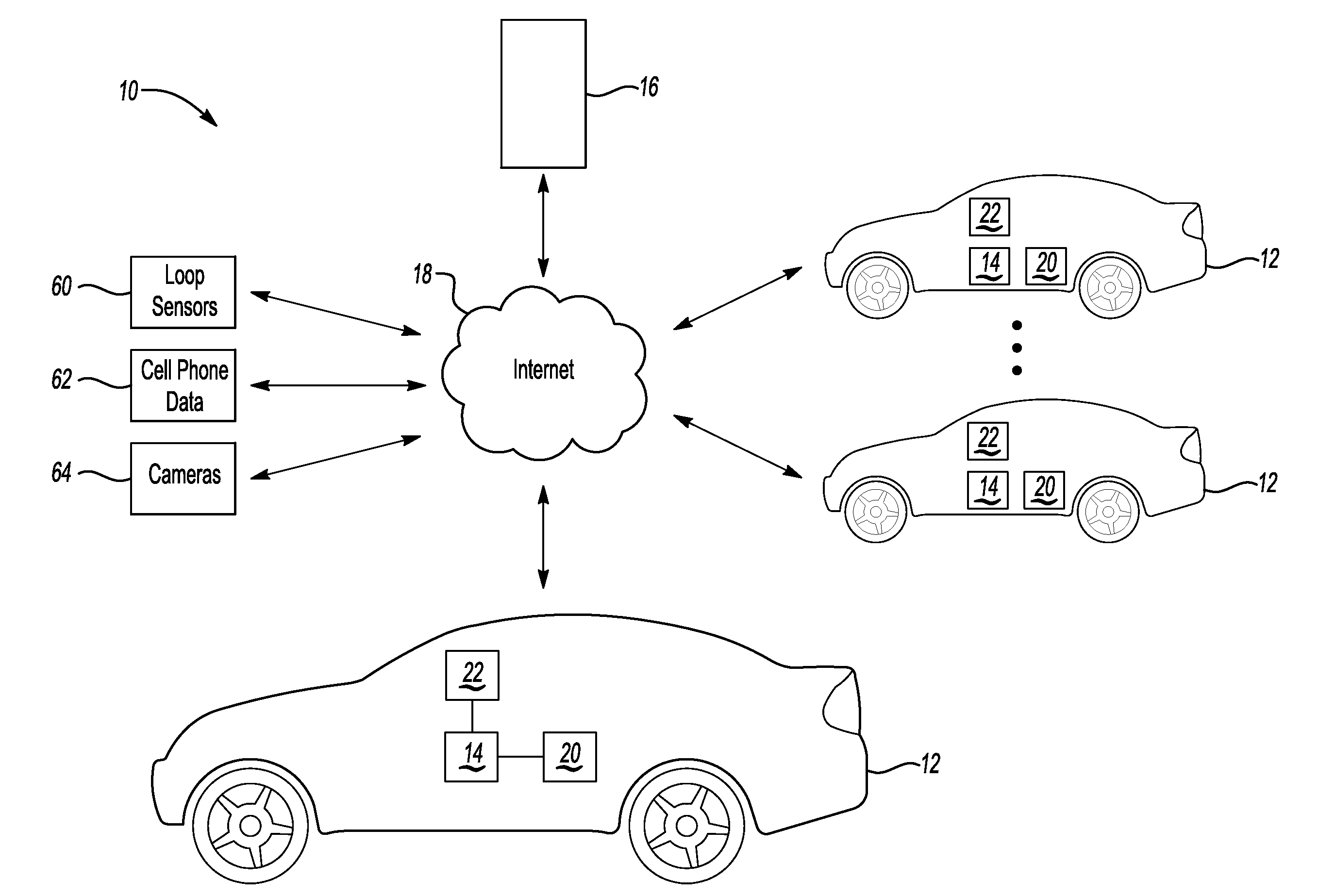
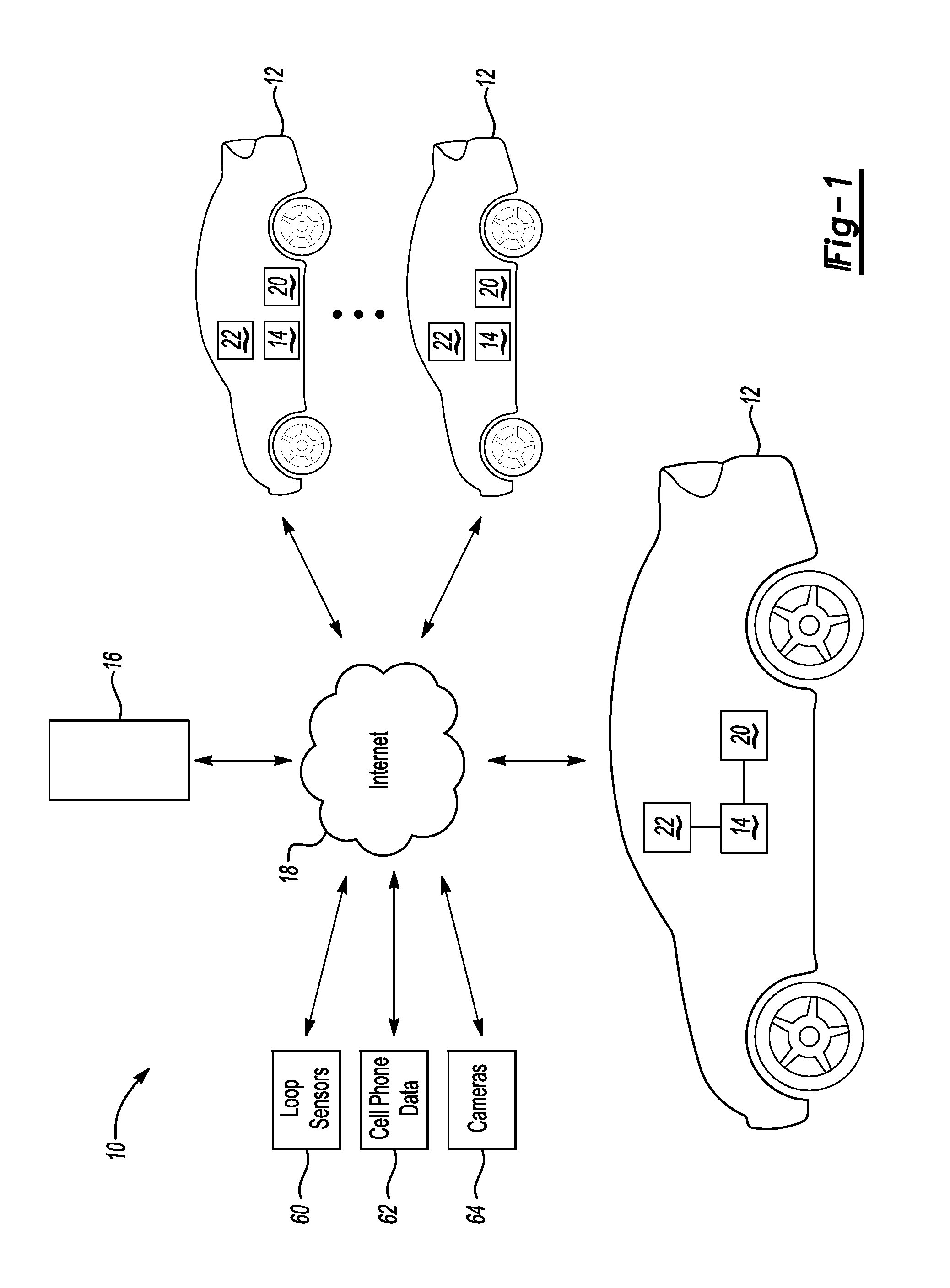
[0022]FIG. 1 schematically illustrates a traffic profiling system 10. A vehicle 12 includes an onboard traffic conditions computer 14 (hereinafter “onboard device”). In one example the onboard device 14 includes some or all of the features in the commercially available iLane® product (see hwww.ilane.com) and / or the commercially available DriveSync® product (see www.drivesync.com). A server 16 is operable to communicate wirelessly with the onboard device 14 via a wide-area network, such as the Internet 18, or a private network or channel. Similar onboard devices 14 are installed on numerous vehicles 12 in the same geographic area and also communicate with the server 16. The server 16 may also receive traffic information from loop sensors 60, cell phone data 62, cameras 64 or other known sources of traffic information, which can be fused with information from the onboard devices 14.

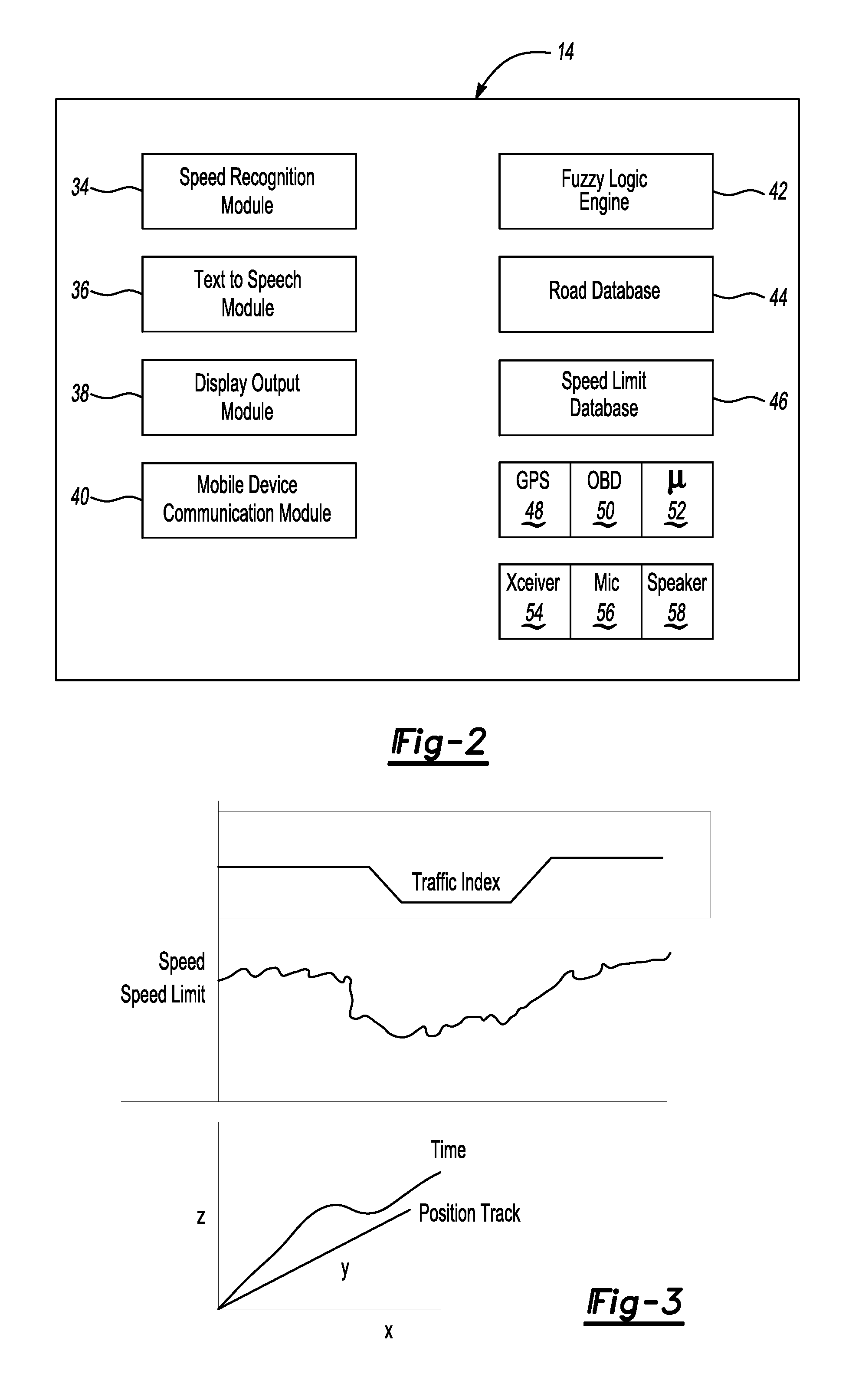
[0023]The onboard device 14 is schematically illustrated in greater detail in FIG. 2. The onboard device...


PUM


Abstract

A method for monitoring travel by a vehicle includes monitoring location of a vehicle as it travels along a plurality of routes from each of a plurality of origins to a plurality of destinations. Frequently-traveled routes are determined from the monitored location of the vehicle. The frequently-traveled routes are displayed to the user. Current traffic conditions may also be displayed on routes between the current location of the vehicle and potential destinations, which are determined based upon previous destinations, contacts, or calendar events.

Description

BACKGROUND OF THE INVENTION[0001]This application relates to trip time computation, and more specifically to a system for computing trip time that includes traffic profiling and road condition-based computation with localized and cooperative assessment.[0002]Previous traffic determination systems have estimated traffic using triangulated positioning of cell phones to determine a speed at which a cell phone moves. There are many limitations and drawbacks in the current systems. For example, if a phone moves quite slowly, it may be assumed that a driver carrying the phone is driving in traffic.SUMMARY OF THE INVENTION[0003]A method for notifying a user about traffic including the step of determining an origin and path of the user. A destination of the user is also determined. Traffic conditions between the origin and the destination are determined. The user is notified of the relevant traffic conditions. Many ways of determining a destination of the user are disclosed. Several optiona...

Claims


Application Information

Patent Timeline
IPC IPC(8): G08G1/00
CPCG08G1/00G08G1/096811G08G1/0112
Inventor BASIR, OTMAN A.
Owner APPY RISK TECH LTD
Why Eureka
Try Eureka