Method of Forming U-Shaped Insert and Inserting About Goods in Container

a technology of u-shaped inserts and containers, which is applied in the direction of packaging foodstuffs, packaging goods types, manufacturing tools, etc., can solve the problem that the panel is still burdensome to be properly ben

Active Publication Date: 2013-09-12
AMF AUTOMATION TECH
View PDF11 Cites 53 Cited by
  • Summary
  • Abstract
  • Description
  • Claims
  • Application Information

AI Technical Summary

Benefits of technology

[0012]The tool that is placed at the end of an arm of a robot may include a vacuum plenum housing with at least one vacuum retriever extending down from the vacuum plenum housing for engaging and picking the work products. The vacuum retriever may be suction cups or suction bellows that contact and adhere to the goods that are to be packed in the shipping container. The same vacuum retrievers may be used for engaging and picking the intermediate portion of the work product so that it may lift the work product away from a supply of the work products, and move the work product from the supply toward the shipping containers.

Problems solved by technology

While the use of score lines on the panels assist in forming the panel into a U-shape, it is still burdensome for the panels to be properly bent and inserted into the containers by hand in a large volume continuous packing operation.

Method used


Image

  • Method of Forming U-Shaped Insert and Inserting About Goods in Container
  • Method of Forming U-Shaped Insert and Inserting About Goods in Container
  • Method of Forming U-Shaped Insert and Inserting About Goods in Container

Examples


Embodiment Construction

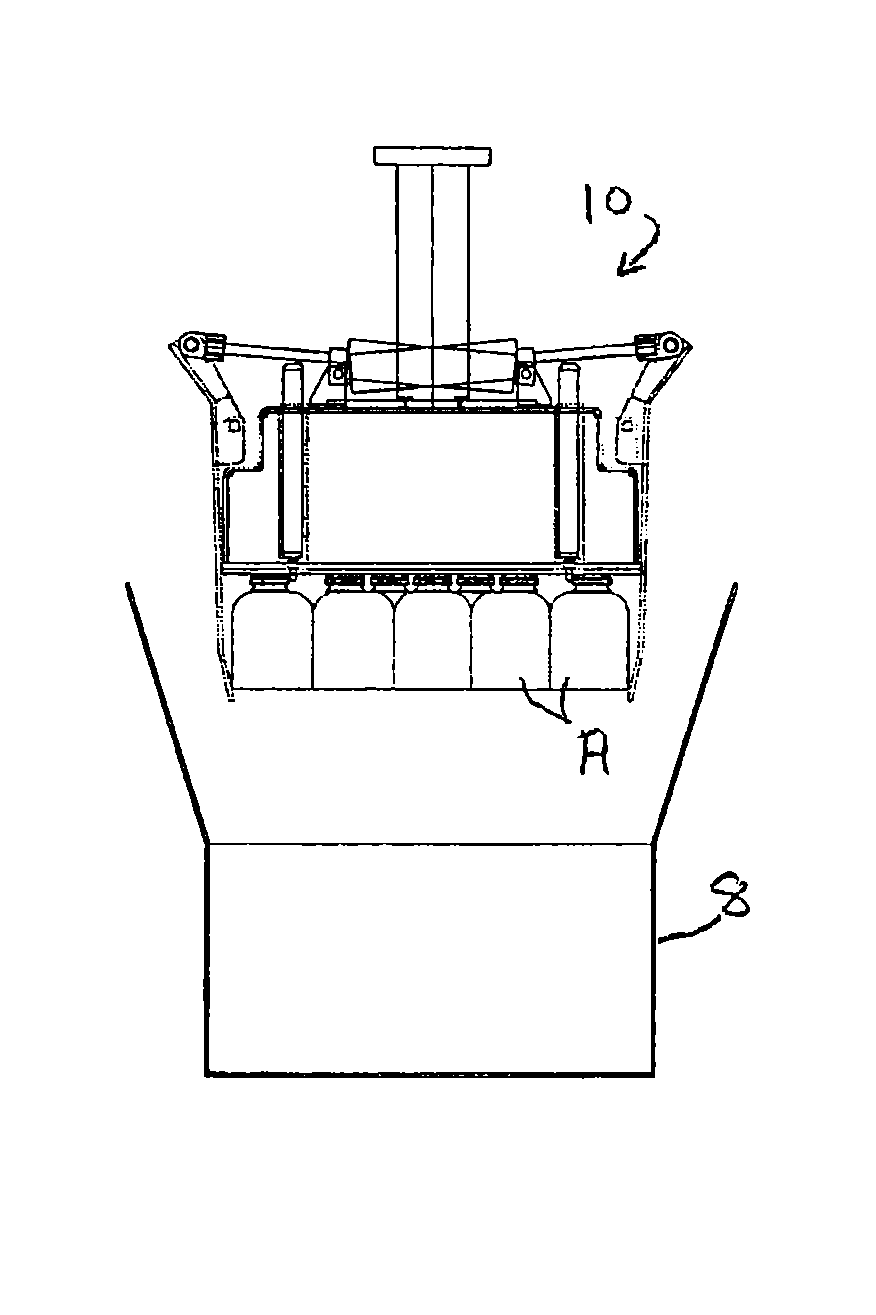
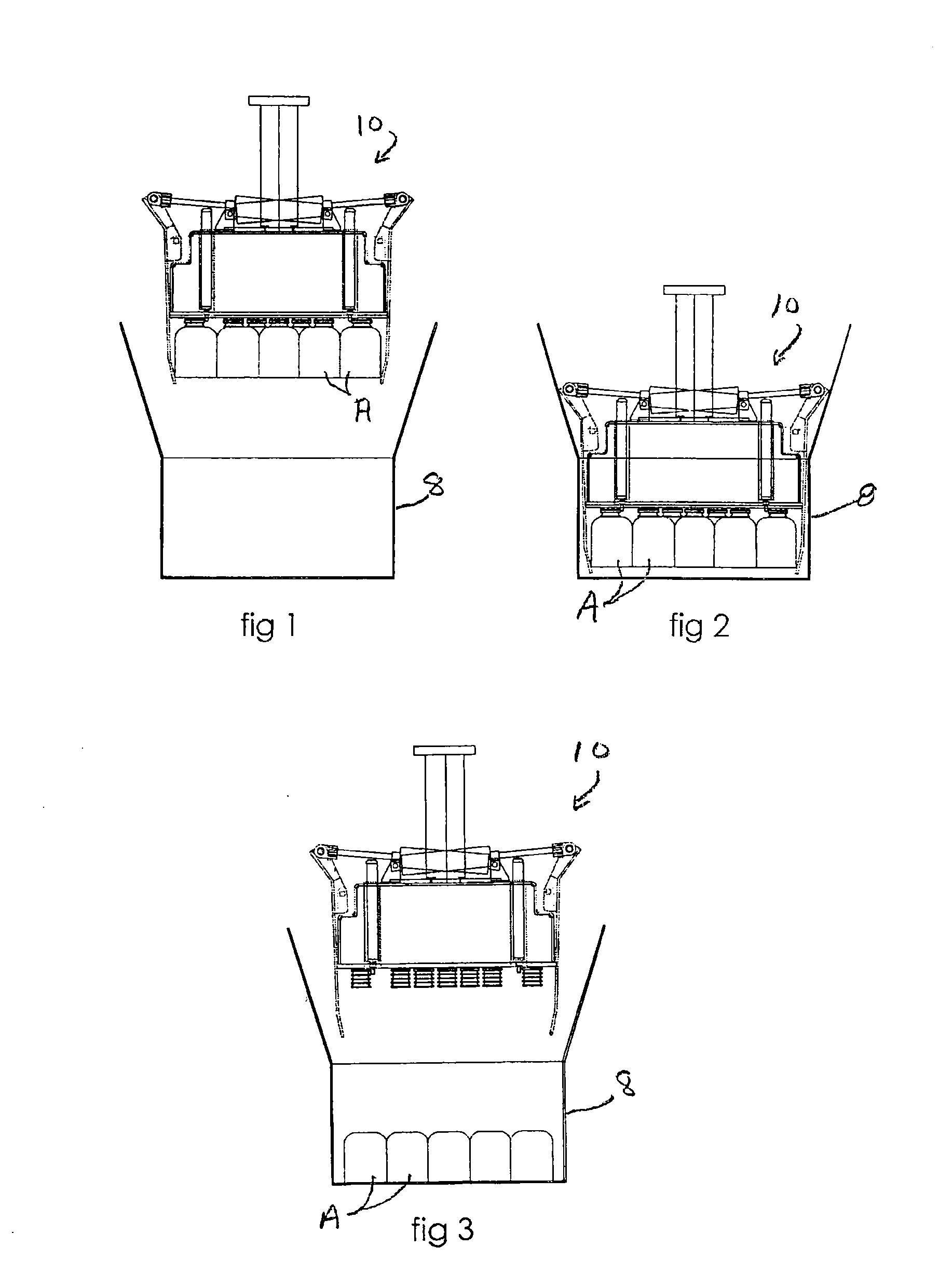
[0020]Referring now in more detail to the drawings, in which like numerals indicate like parts throughout the several views, FIGS. 1-3 illustrate the sequence of placing goods A in a shipping container 8, in which the end of arm tool 10 has picked the goods, such as loaves of bread that are soft and are likely to be damaged by applying the weight of other loaves stacked on them and has moved the goods over the shipping container 8 (FIG. 1). The tool 10 is lowered (FIG. 2) to place the goods A on the bottom of the container, and then raised to leave the goods in the shipping container (FIG. 3). This is conventional in the art.

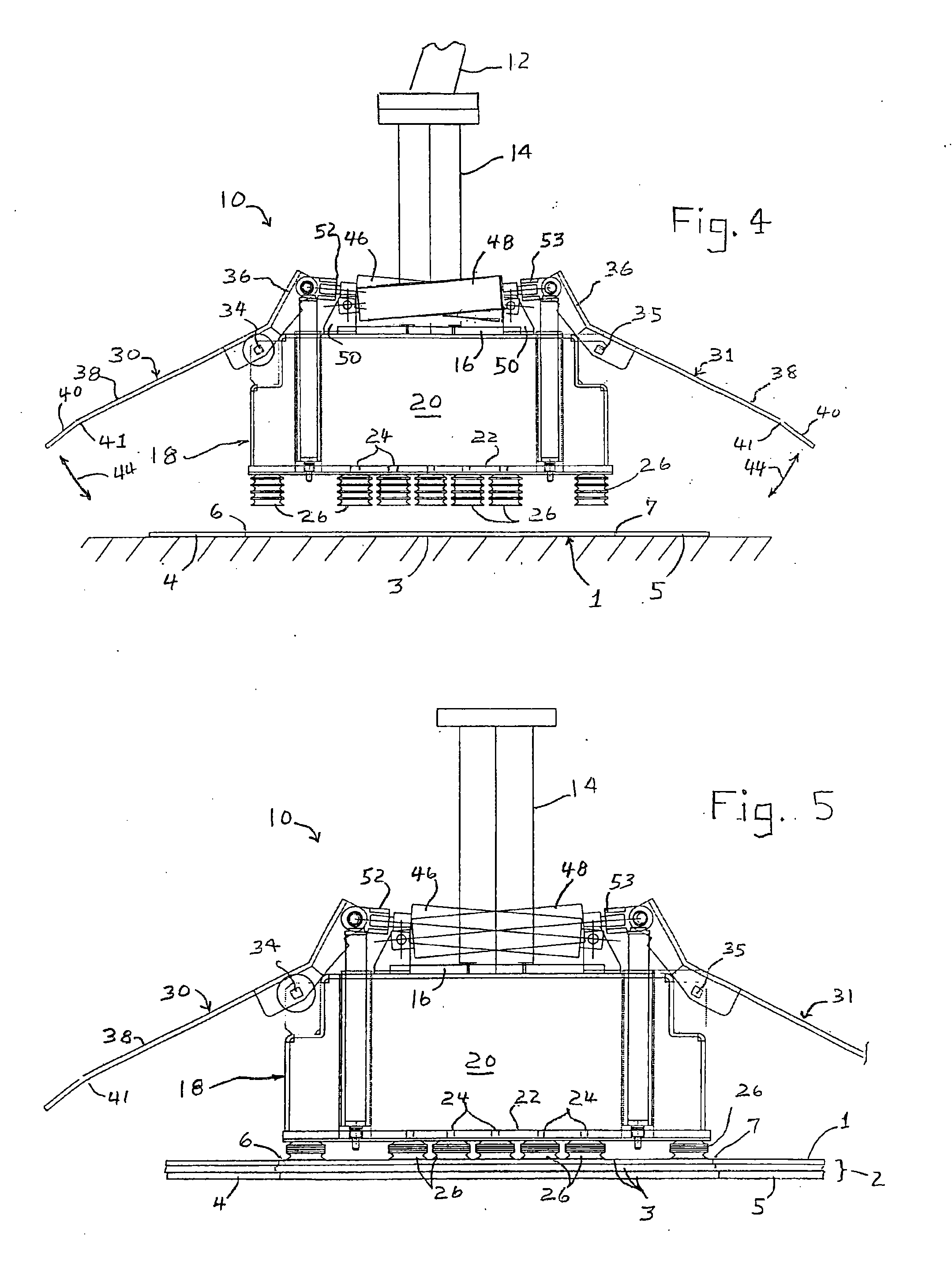
[0021]FIGS. 4-10 illustrate the sequence of picking and forming the work product, inserting the work product in the shipping container, and then withdrawing from the shipping container.

[0022]FIG. 4 illustrates the side view of an end of arm tool 10 that is connected to the arm of a robot 12. The robot arm 12 is shown in FIG. 4 as holding the end of arm tool 10 i...


PUM

PropertyMeasurementUnit
sizeaaaaaaaaaa
lengthaaaaaaaaaa
heightaaaaaaaaaa

Abstract

End of arm tool (10) is used to load goods A and B in two layers in a packing container (8), with a packing insert positioned between the layers. The tool (10) also grasps a packing insert in the form of a flat sheet, bends the ends of the packing sheet downwardly to form an inverted U shape, and then inserts the packing insert in a straddling relationship about the lower layer of goods A, to protect the lower layer of goods from the weight applied by the upper layer of goods B.

Description

CROSS REFERENCE TO RELATED APPLICATION[0001]This is a division of U.S. patent application Ser. No. 12 / 786,779, filed May 25, 2010 in the U.S. Patent & Trademark OfficeTECHNICAL FIELD[0002]The present disclosure concerns a robotic packaging apparatus and method, including an end effector for picking a work product, bending the oppositely extending lateral sides of the work product to form a U-shape, and placing the U-shaped product in a container.BACKGROUND OF THE DISCLOSURE[0003]In the packing of goods in multiple levels in a box or other shipping container, it may be desirable to have a packing insert placed in the shipping container that extends between levels of the goods in the container to avoid the weight of the goods in an upper level from bearing against the goods below. This also tends to strengthen the container when several of the containers are stacked one upon another. For example, packing inserts may be used in containers for protecting food products, products that com...

Claims


Application Information

Patent Timeline
Patent Type & Authority Applications(United States)
IPC IPC(8): B65B5/02
CPCB25J15/0052B25J15/024B65B5/02B66C1/0243B66C1/58B25J15/0616B65B41/06B65B43/24B65B5/06B65B5/105B65B25/16B65B61/207
Inventor LOMERSON, JR., ROLAND
Owner AMF AUTOMATION TECH
Why Eureka
Try Eureka