Wiring dressing rings

a technology for wire dressing rings and wire bundles, applied in the direction of insulated cables, cables, insulated conductors, etc., can solve the problems of not intended summary, achieve the effect of simple, quick, and effortless action, and avoid frustration, tediousness, and time wasted

Inactive Publication Date: 2013-09-12
SUITER ROBERT R
View PDF18 Cites 15 Cited by
  • Summary
  • Abstract
  • Description
  • Claims
  • Application Information

AI Technical Summary

Benefits of technology

[0010]In one exemplary embodiment, a cable dressing ring is provided, which is separated in two halves that are associated by a joint mechanism (e.g., a hinge) at one end, such that the ring can be opened and closed by a user as needed, and that are securable to each other by a locking mechanism, such that the user may easily lock and unlock the ring as needed; and having a plurality of locking cable holders on the outside circumference of the ring. Thus, an advantage is that there is no frustration, tediousness, and time wasted associated with the holding of the two halves of the ring together when needed. A simple, quick, and effortless action (e.g., a simple push), by the user, locks the ring, thus obtaining a robust tool to pull on. Another advantage is that the outer cables of a bundle lock into the cable holders, thus eliminating the need for the laborious and frustrating process of securing the cables to the ring using tape or Velcro.

Problems solved by technology

Moreover, this Summary is not intended for use as an aid in determining the scope of the claimed subject matter.

Method used


Image

  • Wiring dressing rings
  • Wiring dressing rings
  • Wiring dressing rings

Examples


Embodiment Construction

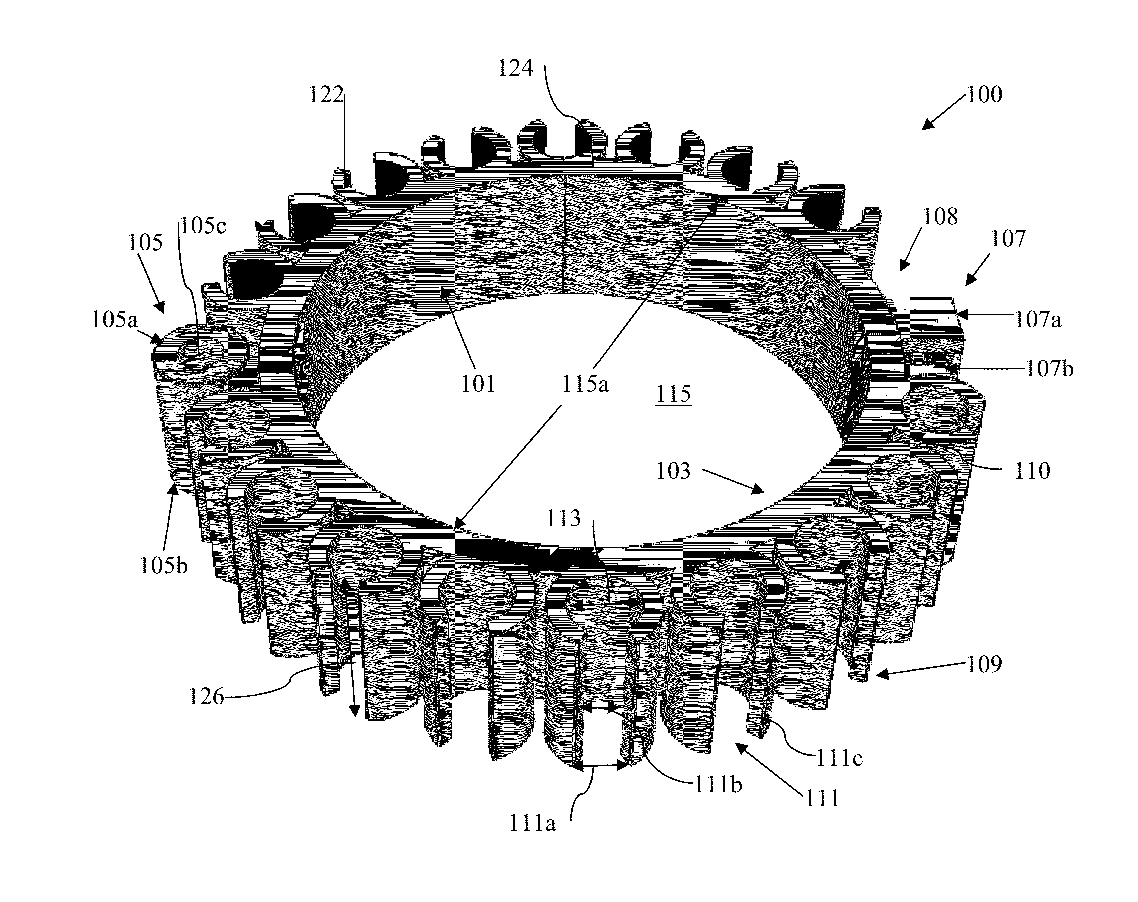
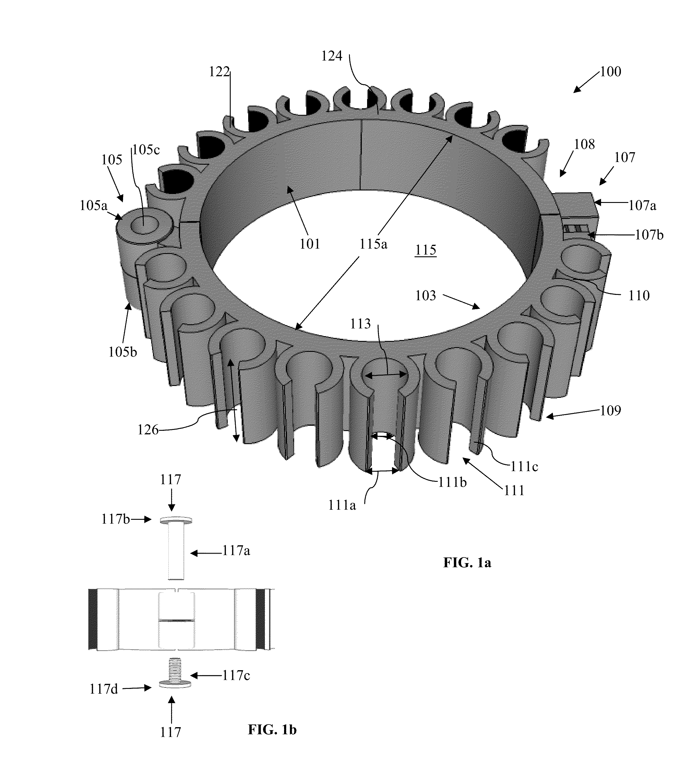
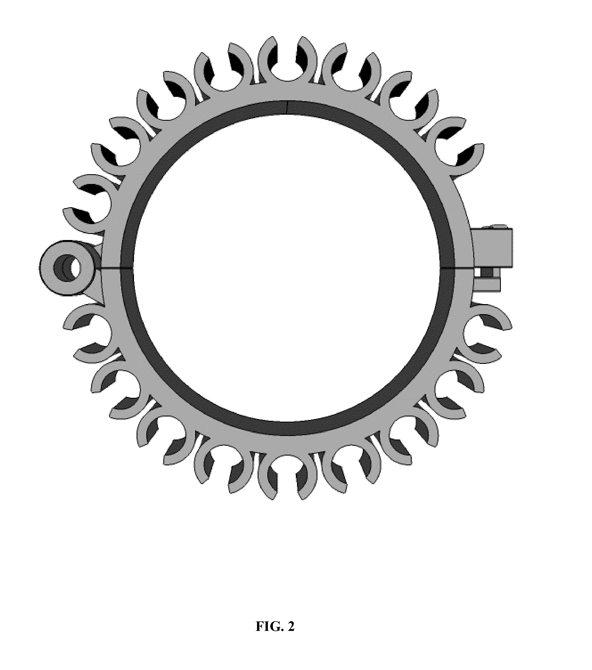
[0019]What follows is a detailed description of the preferred embodiments of the invention in which the invention may be practiced. Reference will be made to the attached drawings, and the information included in the drawings is part of this detailed description. The specific preferred embodiments of the invention, which will be described herein, are presented for exemplification purposes, and not for limitation purposes. It should be understood that structural and / or logical modifications could be made by someone of ordinary skills in the art without departing from the scope of the invention. Therefore, the scope of the invention is defined by the accompanying claims and their equivalents.

[0020]Throughout this disclosure, the term “wiring dressing ring” is used interchangeably with the following synonymous terms: “cable dressing ring,”“dressing ring,”“dress ring,”“cable ring” and “ring.” Furthermore, the term “wire” and its derivatives are used herein interchangeably with the synon...


PUM

PropertyMeasurementUnit
diameteraaaaaaaaaa
diameteraaaaaaaaaa
diameteraaaaaaaaaa

Abstract

A cable dressing ring for organizing a cable bundle is provided, wherein, the ring is separated in two halves that are associated by a joint mechanism at one end, and that are securable to each other by a locking mechanism at the other end, such that a user may lock the ring when needed to clamp the ring around the inner cables of the bundle, and wherein, the ring has a plurality of self-locking cable holders on the outside circumference of the ring, for holding the outer cables of the bundle organized while pulling the ring toward one end of the bundle.

Description

CROSS-REFERENCE TO RELATED APPLICATIONS[0001]This application claims the benefit of U.S. Provisional Application No. 61 / 609,788, filed Mar. 12, 2012, which is hereby incorporated by reference, to the extent that it is not conflicting with the present application.STATEMENT REGARDING FEDERALLY SPONSORED RESEARCH OR DEVELOPMENT[0002]Not ApplicableREFERENCE TO SEQUENCE LISTING, A TABLE, OR A COMPUTER PROGRAM LISTING COMPACT DISC APPENDIX[0003]Not ApplicableBACKGROUND OF THE INVENTION[0004]1. Field of the Invention[0005]The invention relates a tool for neatly organizing cable bundles.[0006]2. Description of the Related Art[0007]When cabling technicians pull cables (or wires) throughout a building, they pull from a computer room for example, and they typically end up with a large bundle of cables. The large bundle of cables, throughout the building, as well as all the cables throughout the computer room, and / or throughout a computer rack, has to be neatly organized so that the job appears...

Claims


Application Information

Patent Timeline
Patent Type & Authority Applications(United States)
IPC IPC(8): H01B17/00
CPCH02G3/32H02G1/00
Inventor SUITER, ROBERT R.
Owner SUITER ROBERT R
Why Eureka
Try Eureka