Tubular heat exchange systems

a heat exchange system and tubular technology, applied in the direction of blade accessories, machine/engine, climate sustainability, etc., can solve the problems of inconvenient use, inconvenient use, and inconvenient use,

Active Publication Date: 2013-09-12
HONEYWELL INT INC
View PDF12 Cites 105 Cited by
  • Summary
  • Abstract
  • Description
  • Claims
  • Application Information

AI Technical Summary

Problems solved by technology

Plate-fin architectures, while relatively inexpensive to manufacture, do not result in favorable weight and performance characteristics.
Tubular architectures, while relatively more efficient than plate-fin architectures,

Method used


Image

  • Tubular heat exchange systems
  • Tubular heat exchange systems
  • Tubular heat exchange systems

Examples


Embodiment Construction

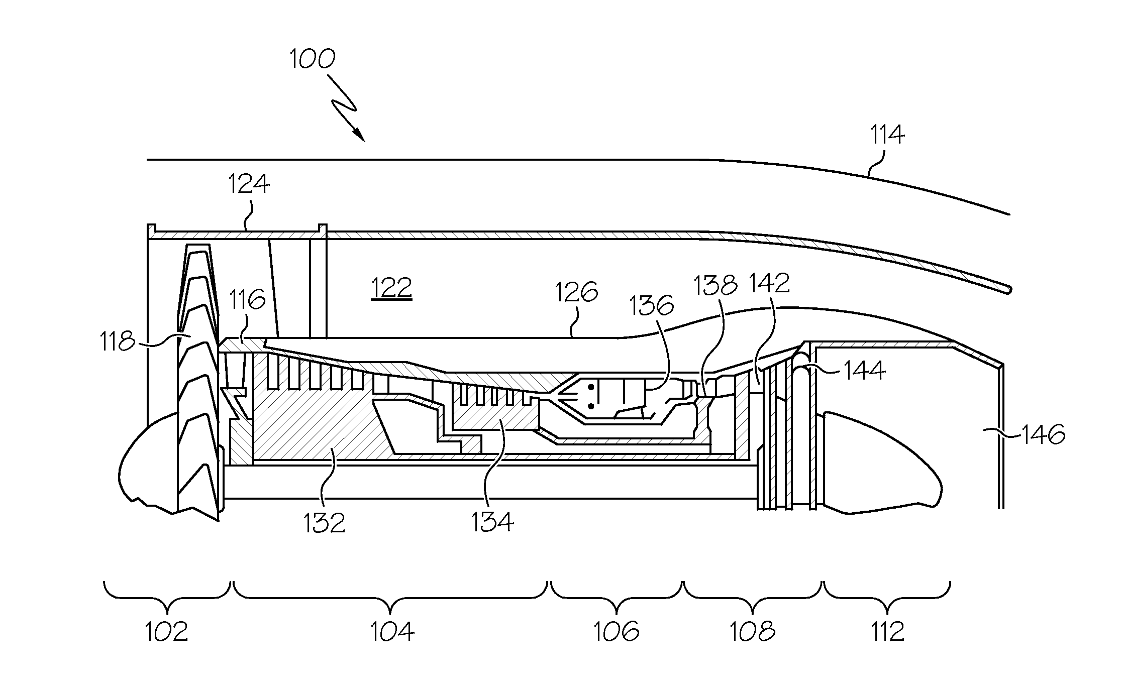
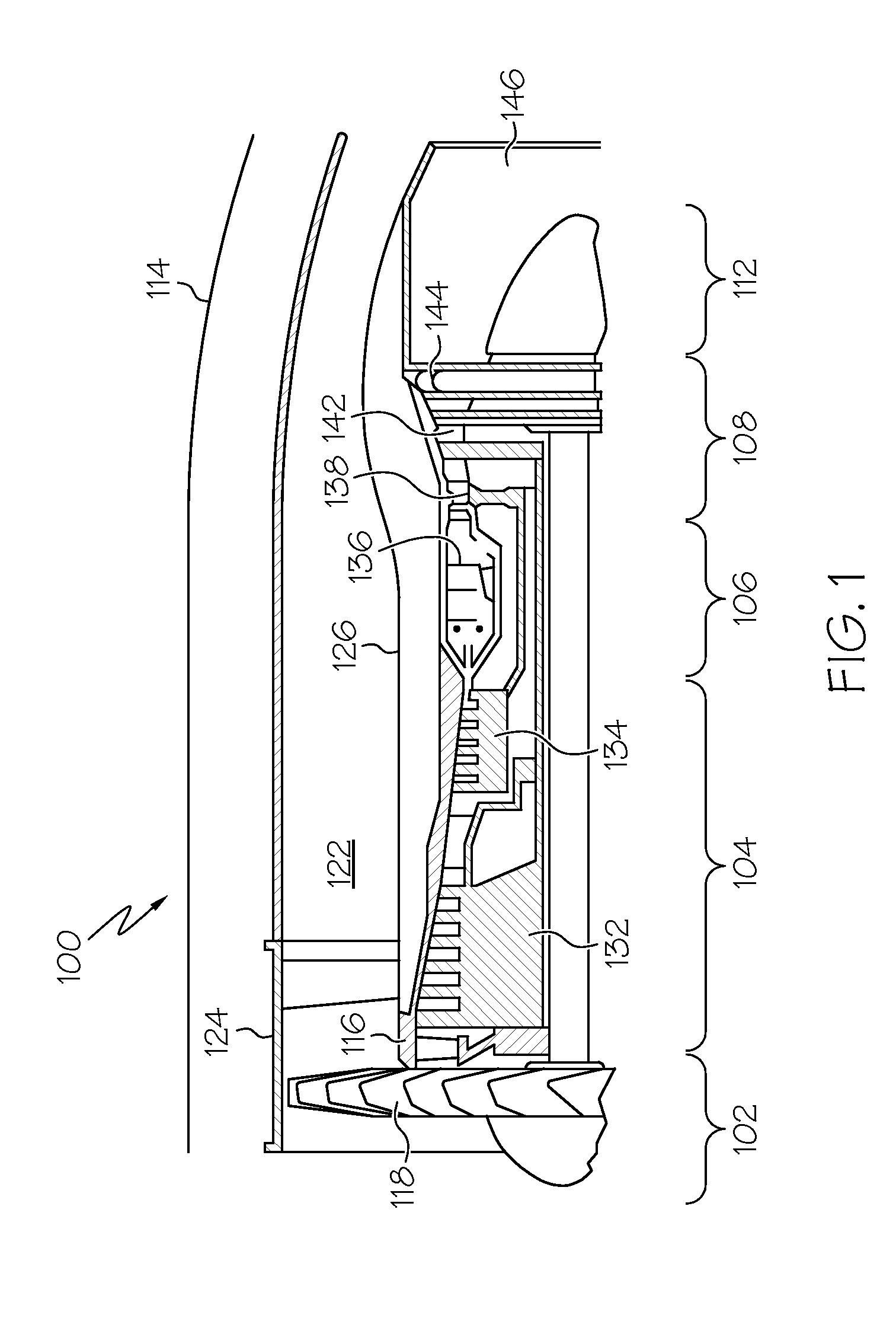
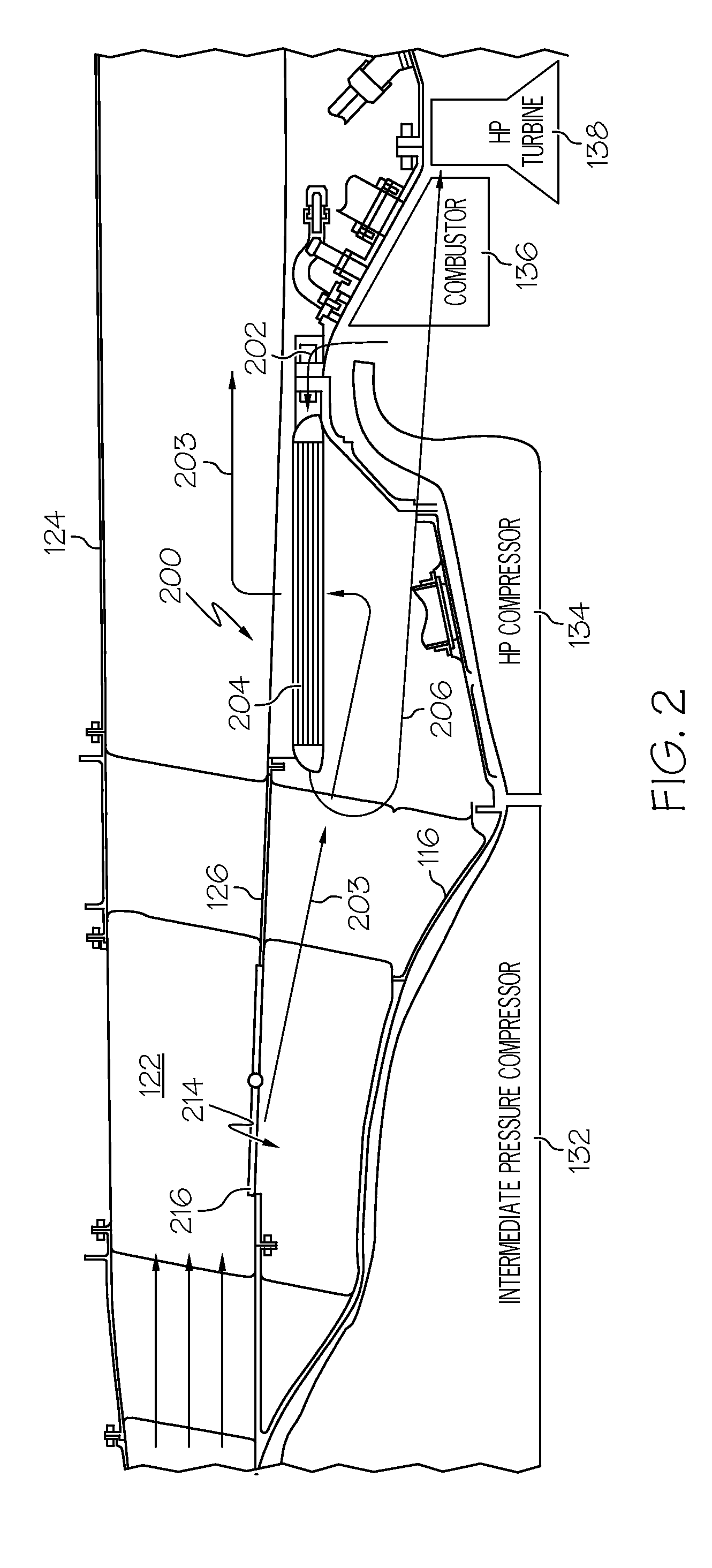
[0023]The following detailed description is merely exemplary in nature and is not intended to limit the invention or the application and uses of the invention. As used herein, the word “exemplary” means “serving as an example, instance, or illustration.” Thus, any embodiment described herein as “exemplary” is not necessarily to be construed as preferred or advantageous over other embodiments. Furthermore, as used herein, numerical ordinals such as “first,”“second,”“third,” etc., such as first, second, and third heat exchangers, simply denote different singles of a plurality unless specifically defined by language in the appended claims. All of the embodiments and implementations of the heat exchange systems described herein are exemplary embodiments provided to enable persons skilled in the art to make or use the invention and not to limit the scope of the invention which is defined by the claims. Furthermore, there is no intention to be bound by any expressed or implied theory pres...


PUM

PropertyMeasurementUnit
Thicknessaaaaaaaaaa
Heataaaaaaaaaa

Abstract

A heat exchange system includes a first flow passage and a second flow passage. The heat exchange system is configured to transfer heat between a first fluid flowing through the first flow passage and a second fluid flowing through the second flow passage. The first flow passage includes an inlet header, a plurality of tubes, and an outlet header. The inlet header includes a plurality of header-tube transition portions configured to allow the first fluid to flow from the inlet header and into the tubes, the plurality of header-tube transition portions each including a smoothly curved inlet portion and a tapered tube connection portion.

Description

TECHNICAL FIELD[0001]The present disclosure generally relates to heat exchange systems, and more particularly, in one implementation, relates to heat exchange systems for use in gas turbine engines.BACKGROUND[0002]In the field of gas turbine technology, a great deal of effort has been directed toward improving thermodynamic efficiency by operating gas turbine engines at increasing temperatures. As such, numerous heat exchange systems have been developed for directing heat within an engine to components where such heat is beneficial to the operating performance of the engine, while other heat exchange systems have been developed for directing heat away from engine components that normally cannot tolerate such high temperatures.[0003]In one example, a class of heat exchange systems known as recuperators have been developed to recover heat from the engine exhaust, which is otherwise wasted energy, and redirect the recovered engine exhaust heat to the combustion portion of the engine, t...

Claims


Application Information

Patent Timeline
IPC IPC(8): F28F9/02B23K26/00F01D25/12F28F13/12
CPCF02C7/10F02C7/08F28F9/0263F28F9/0282F02K3/115F28D7/1669F28D21/001F05D2260/213Y02T50/675F28F9/26B22F2998/10B33Y80/00Y02P10/25Y02T50/60B22F10/28B22F10/66B22F10/73B22F10/64B22F2003/247B22F2003/248B22F3/15F28F13/125
Inventor KINGTON, HARRY LESTERMORRIS, MARK C.GODFREY, DONALD G.MEIER, JOHNLO, CHARLES
Owner HONEYWELL INT INC
Why Eureka
Try Eureka