Assembly type accessory
a technology of assembly type and accessory, applied in the direction of eye fasteners, hook fasteners, bracelets, etc., can solve the problems of reducing the marketability of accessories, deteriorating esthetic beauty, and conventional assembly type accessories as described above, and achieve the effect of improving esthetic beauty
- Summary
- Abstract
- Description
- Claims
- Application Information
AI Technical Summary
Benefits of technology
Problems solved by technology
Method used
Image
Examples
first embodiment
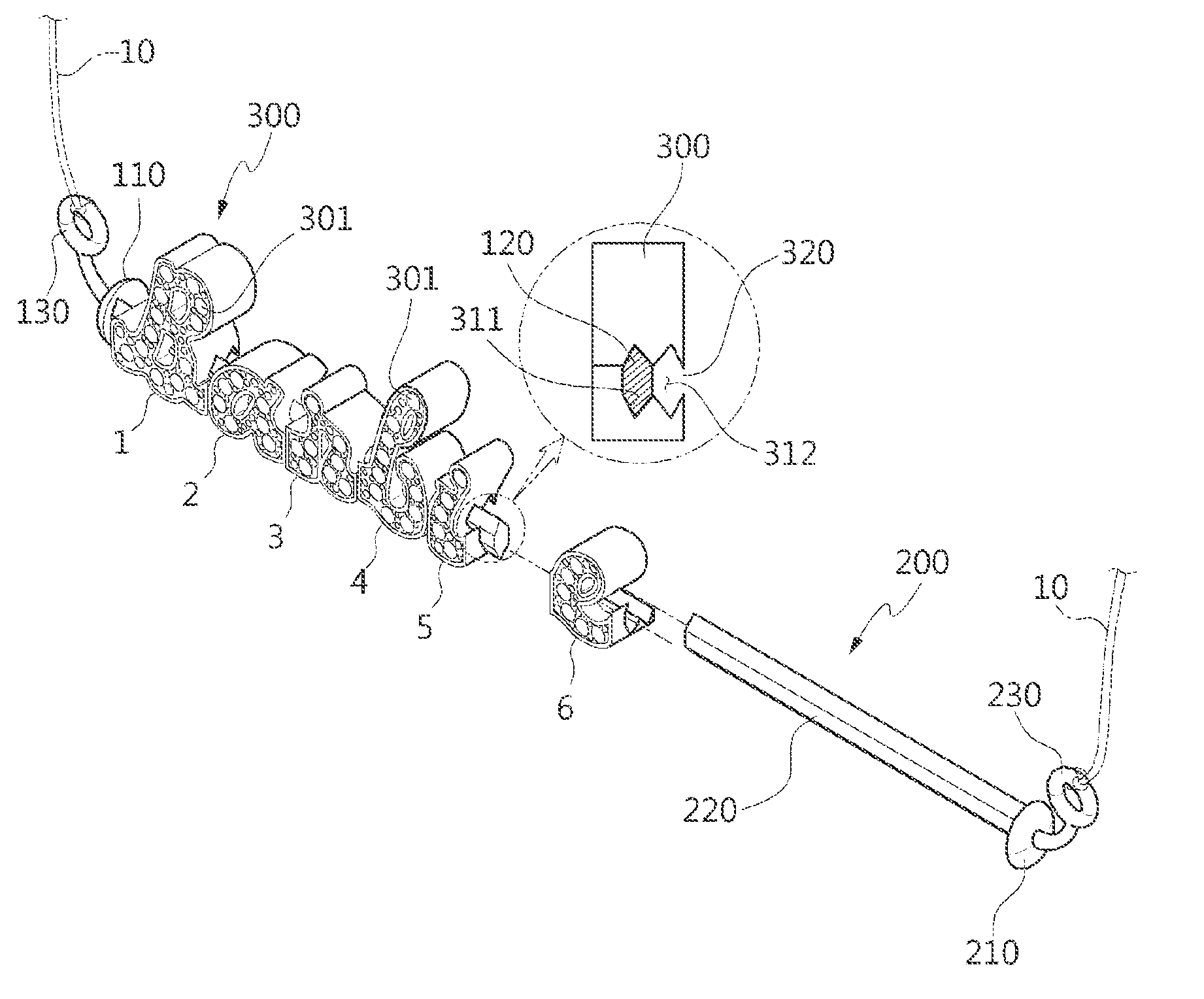
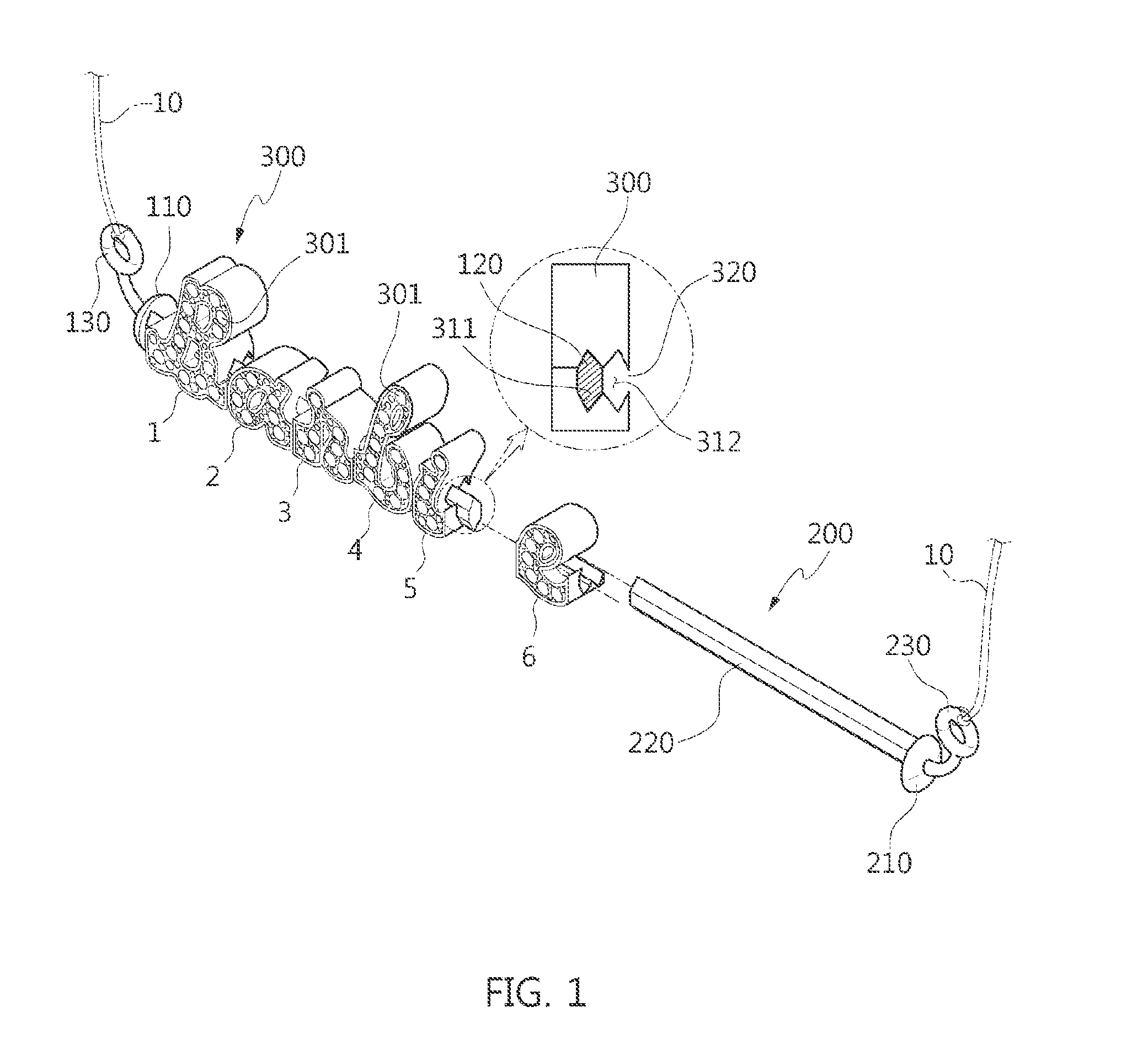
[0039]First, the present invention is explained with reference to FIG. 1 through FIG. 4.
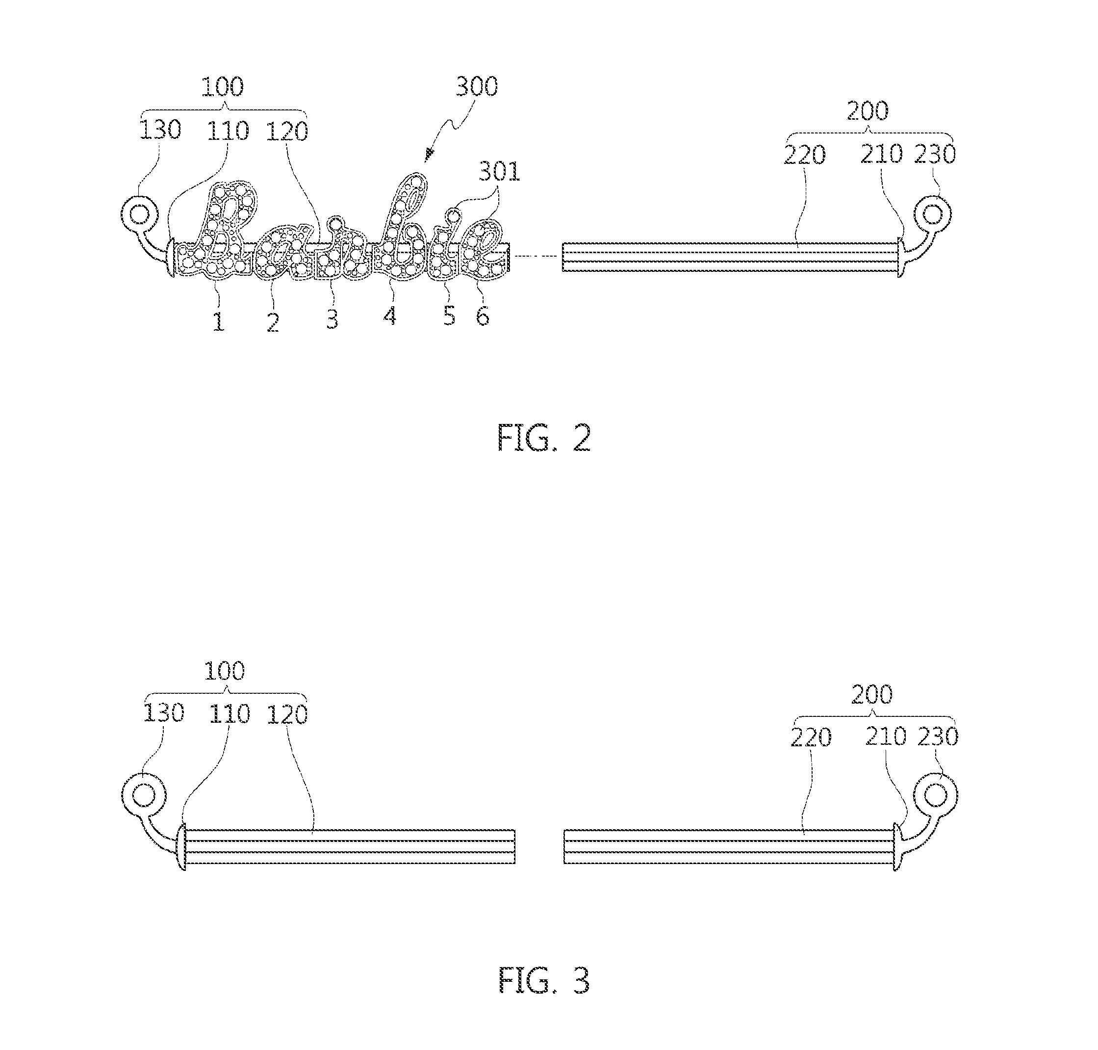
[0040]As described above, the first embodiment of the present invention shows an assembly type initial necklace. The assembly type accessory according to the first embodiment includes a rail part and initial blocks 300. The rail part is formed of a first rail 100 and a second rail 200.
[0041]The first rail 100 is formed of a first support plate 110, and a first insertion rod 120 which is formed to extend to one side of the first support plate 110. The first support plate 110 functions to support and fix the initial blocks 300 inserted into the first insertion rod 120.
[0042]A ring for a necklace 130 is formed in another side of the first support plate 110 so as to connect a string for a necklace 10.
[0043]The second rail 200 is formed of a second support plate 210, and a second insertion rod 220 which is formed to extend to one side of the second support plate 210. The second support plate 210 funct...
second embodiment
[0059]Next, the present invention will be explained with reference to FIG. 5 through FIG. 7.
[0060]As described above, the second embodiment of the present invention shows the assembly type initial earring. The assembly type accessory according to the second embodiment includes the rail part formed of the first rail 100 and the second rail 200 and the initial blocks 300.
[0061]Since the first rail 100, the second rail 200, and the initial blocks 300 perform almost identical functions with those of the first embodiment as described above, the difference between them will be explained.
[0062]In the second embodiment of the present invention, instead of the rings for the necklace 130 and 230 of the first embodiment of the present invention as described above, to perform the function of an earring, grooves for an earring 400 which are spaced apart from each other are formed on the outer circumferential surface of the first rail 100 or the second rail 200 at fixed intervals.
[0063]As illustr...
third embodiment
[0068]Next, the present invention will be explained with reference to FIG. 8 and FIG. 9.
[0069]As previously described, the third embodiment of the present invention shows the assembly type initial ring. The assembly type accessory according to the third embodiment includes the rail part formed of the first rail 100, the second rail 200, and a third rail 600, and the initial blocks 300.
[0070]The first rail 100 is formed of the first support plate 110, and the first insertion rod 120 which is formed to extend to one side of the first support plate 110. The second rail 200 is formed of the second support plate 210, and the second insertion rod 220 which is formed to extend to one side of the second support plate 210.
[0071]As illustrated in FIG. 8 and FIG. 9, the shapes of the first rail 100 and the second rail 200 are similar to each other.
[0072]The third rail 600 includes a third insertion rod 610 having a predetermined length and is a member which is configured such that a ring 500 i...
PUM
 Abstract
Description
Claims
Application Information
 - R&D
- Intellectual Property
- Life Sciences
- Materials
- Tech Scout
- Unparalleled Data Quality
- Higher Quality Content
- 60% Fewer Hallucinations
Browse by: Latest US Patents, China's latest patents, Technical Efficacy Thesaurus, Application Domain, Technology Topic, Popular Technical Reports.
© 2025 PatSnap. All rights reserved.Legal|Privacy policy|Modern Slavery Act Transparency Statement|Sitemap|About US| Contact US: help@patsnap.com


