Non-hyperbolic correction of seismic data

a seismic data and non-hyperbolic technology, applied in the field of seismic imaging, can solve the problems of static solution not accurately solving the problem of clarifying the data, non-hyperbolicity degrades the seismic image, and seismic events are non-hyperboli

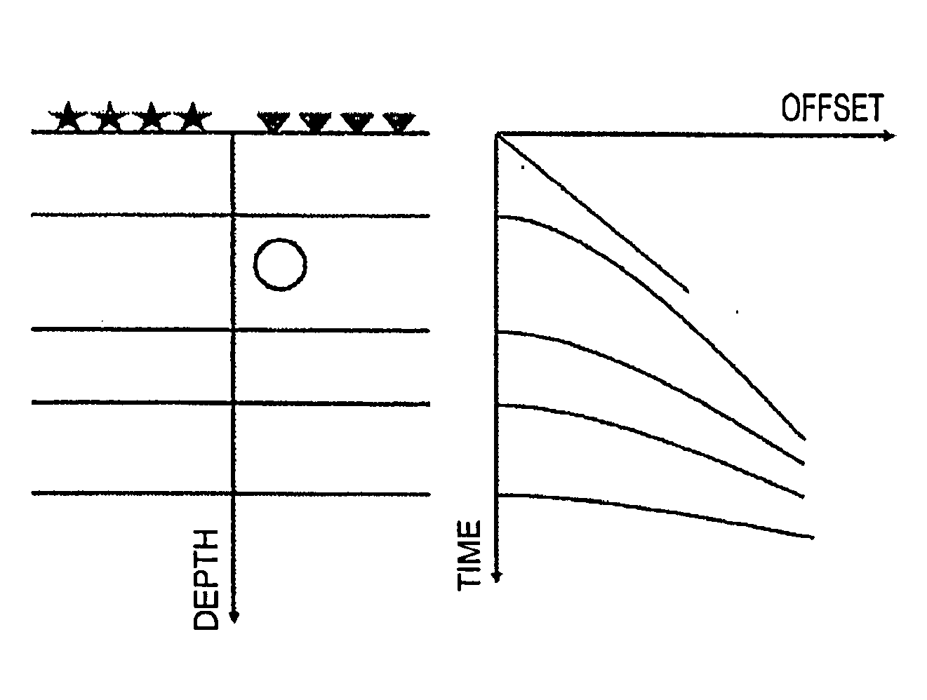
Active Publication Date: 2013-09-19
SAUDI ARABIAN OIL CO
View PDF1 Cites 0 Cited by
  • Summary
  • Abstract
  • Description
  • Claims
  • Application Information

AI Technical Summary

Problems solved by technology

This non-hyperbolicity degrades the seismic image after stacking due to the fact that the anomaly imprint cannot be properly described by the stacking velocity function or static corrections.
However, this is hardly ever the case with land datasets that suffer from the complexities of weathered layers and buried velocity anomalies which cause the seismic events to be non-hyperbolic.
These assumptions don't hold in the case of complex near-surface or buried velocity anomalies and the static solution cannot accurately resolve the problem of clarifying the data.
One limitation of most redatuming algorithms is that they require the use of knowledge of the velocity-depth model of the near-surface which is very difficult to obtain in land datasets.
However, CFP redatuming also has certain limitations, including the following:a. the data above the target horizon is degraded because the redatuming process shifts all the anomalies to those shallower horizons;b. the new dataset after redatuming has an unknown acquisition reference in location / depth that is the target horizon; andc. the new dataset after redatuming is different than the input dataset in reference time, as well as in the move-out behavior of the seismic events.
A static solution therefore cannot resolve this effect, even if trim statics were used, because of the dynamic nature of the problem.
Static corrections will provide a satisfactory resolution for shallow anomalies; however, as is well known, although static corrections might resolve the problem for the very deep horizon, it is at the cost of the horizons closer to the anomaly.
Another problem that arises with buried velocity anomalies is the possibility of having horizons above the anomaly, in which case, it is possible to resolve the problem for the deeper horizons, but the effect of the anomaly will be imposed on the horizons above it.
Another problem is that this new dataset differs from the input data in two important ways.
First, the new dataset has the target horizon flat at zero, which is considered to be undesirable by interpreters of the resultant image because they are used to looking at data from a smoothed surface.

Method used


Image

  • Non-hyperbolic correction of seismic data
  • Non-hyperbolic correction of seismic data
  • Non-hyperbolic correction of seismic data

Examples


example using 2d

Synthetic Data

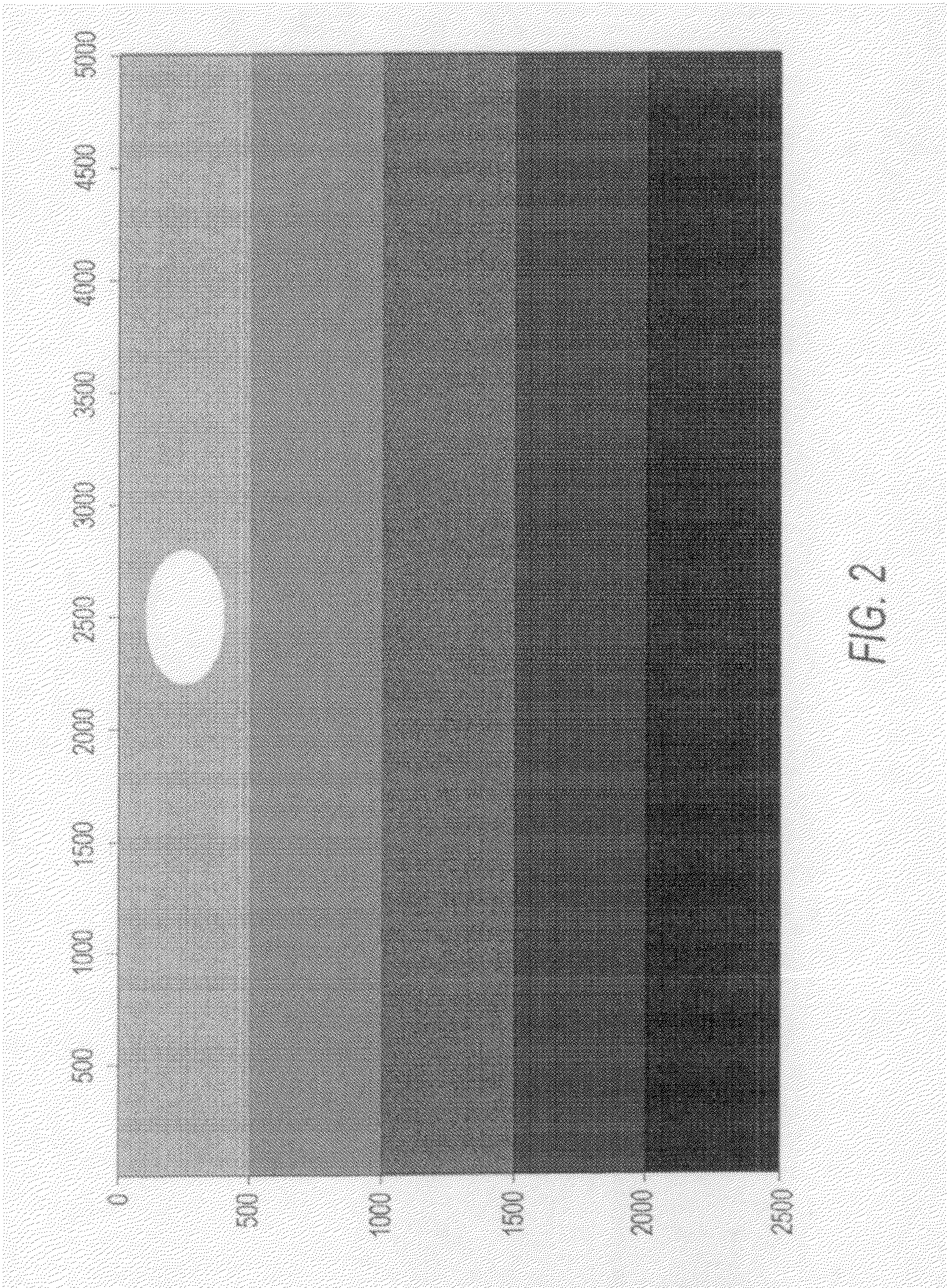
[0049]An acoustic finite difference algorithm was used to create synthetic shot records for the synthetic velocity model depicted in FIG. 9, which represents a subsurface model containing a wadi, several layers with lateral velocity-variations embedded in the near surface and a number of smooth deep reflectors. The sources are located from x=0 m towards x=10000 m. The shot records are modeled with a moving split-spread geometry with an offset range of 4800 m and a source and receiver interval of 20 m. The synthetic shot records have been processed and a horizon-consistent velocity analysis was performed to obtain the brute stack of the data shown in FIG. 10 that depicts the surface stack before applying the NHC method of the present invention.

[0050]FIG. 10 shows that all the horizons from t=0.8 sec and after appear to be broken. This is the result of the block-shaped layers visible in FIG. 9 at around z=600 m. As noted above, these discontinuities cannot be resolved us...


PUM


Abstract

A method for improving seismic images by correction of distortions in the underlying seismic data caused by a near-surface anomaly that produces a non-hyperbolic move-out component of the seismic reflection below the anomaly includes the steps of: a. redatuming the input seismic data to go from the surface to a target horizon using true one-way traveltime operators to provide a first new redatuming dataset; b. redatuming the input seismic data using hyperbolic one-way travel time operators to provide a second new redatuming dataset; and c. redatuming the combination of a first causal part of the first new redatuming dataset and an anti-causal second part of the second redatuming dataset to go from the target horizon back to the surface using hyperbolic one-way traveltime operators to provide a dataset that is referenced to the surface without an imprint of the anomaly.

Description

FIELD OF THE INVENTION[0001]This invention relates to seismic imaging, and in particular to a process for the correction of seismic data to minimize the effect of distortions caused by a near-surface anomaly that produces a non-hyperbolic move-out in the seismic reflection below that anomaly.BACKGROUND OF THE INVENTION[0002]A buried velocity anomaly produces a non-hyperbolic move-out in all the seismic reflection events below that anomaly. This non-hyperbolicity degrades the seismic image after stacking due to the fact that the anomaly imprint cannot be properly described by the stacking velocity function or static corrections. This distortion or deterioration can appear as a defocus or as a break in the seismic image.[0003]Conventional time-imaging techniques such as stacking or migration use stacking velocity to describe the nature of seismic data. Stacking velocity is based on the assumption that all seismic events in the common mid-point domain can be described by hyperbolic fun...

Claims


Application Information

Patent Timeline
Patent Type & Authority Applications(United States)
IPC IPC(8): G01V1/36
CPCG01V1/364G01V1/362G01V2210/52G01V1/28
Inventor AL-MOMIN, ALI AMEENLUO, YIFEI, TONG W.
Owner SAUDI ARABIAN OIL CO
Why Eureka
Try Eureka