Unitary Lanyard and Base for Electronic Surveillance Tag

a technology of electronic surveillance and lanyard, which is applied in the field of unitary lanyard and base for electronic surveillance tags, can solve the problem that the assembly of tags is not convenient for clothing articles, and achieves the effect of convenient us

Active Publication Date: 2013-09-26
BEST SECURITY ACQUISITION LLC
View PDF1 Cites 9 Cited by
  • Summary
  • Abstract
  • Description
  • Claims
  • Application Information

AI Technical Summary

Problems solved by technology

Such a tag assembly is not convenient to utilize for articles of clothing such as leather or for handbags, purses, or the like generally made of other than a one layer of woven fabric.

Method used


Image

  • Unitary Lanyard and Base for Electronic Surveillance Tag
  • Unitary Lanyard and Base for Electronic Surveillance Tag
  • Unitary Lanyard and Base for Electronic Surveillance Tag

Examples


Embodiment Construction

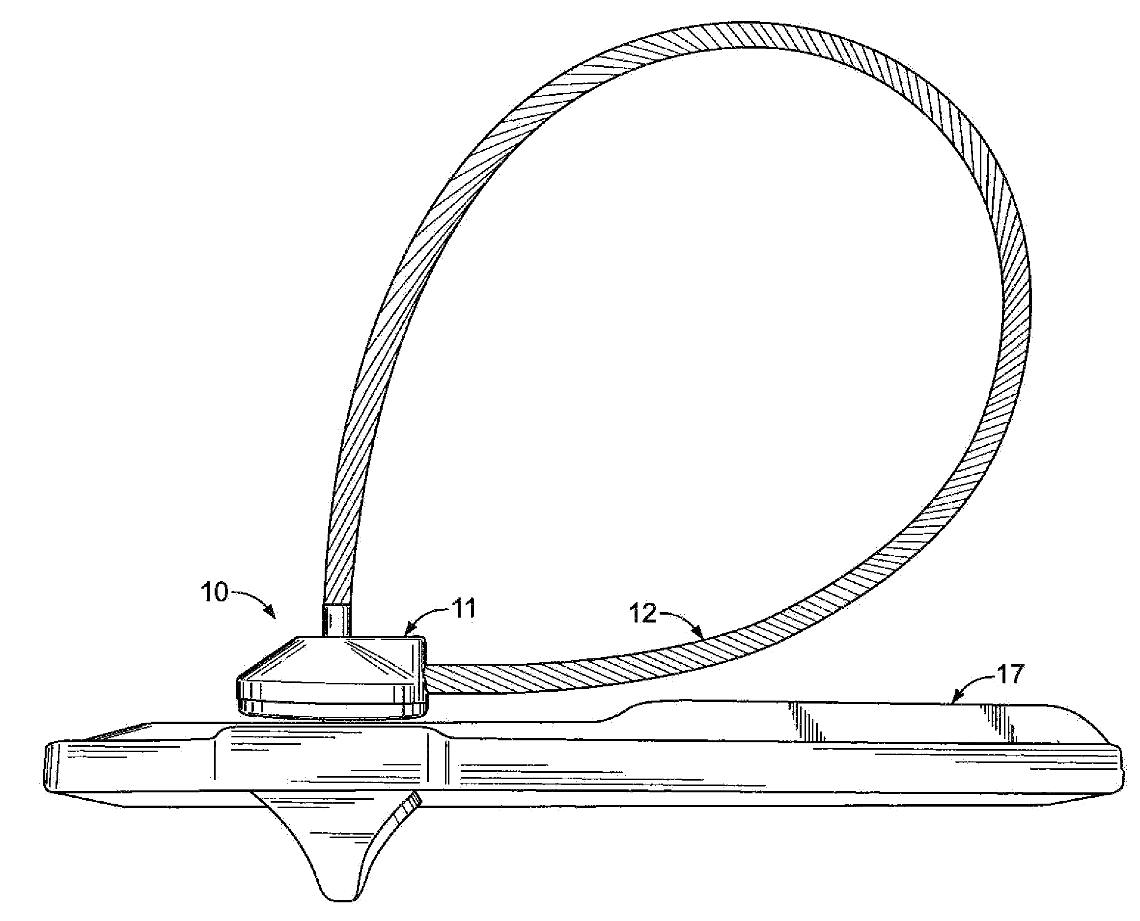
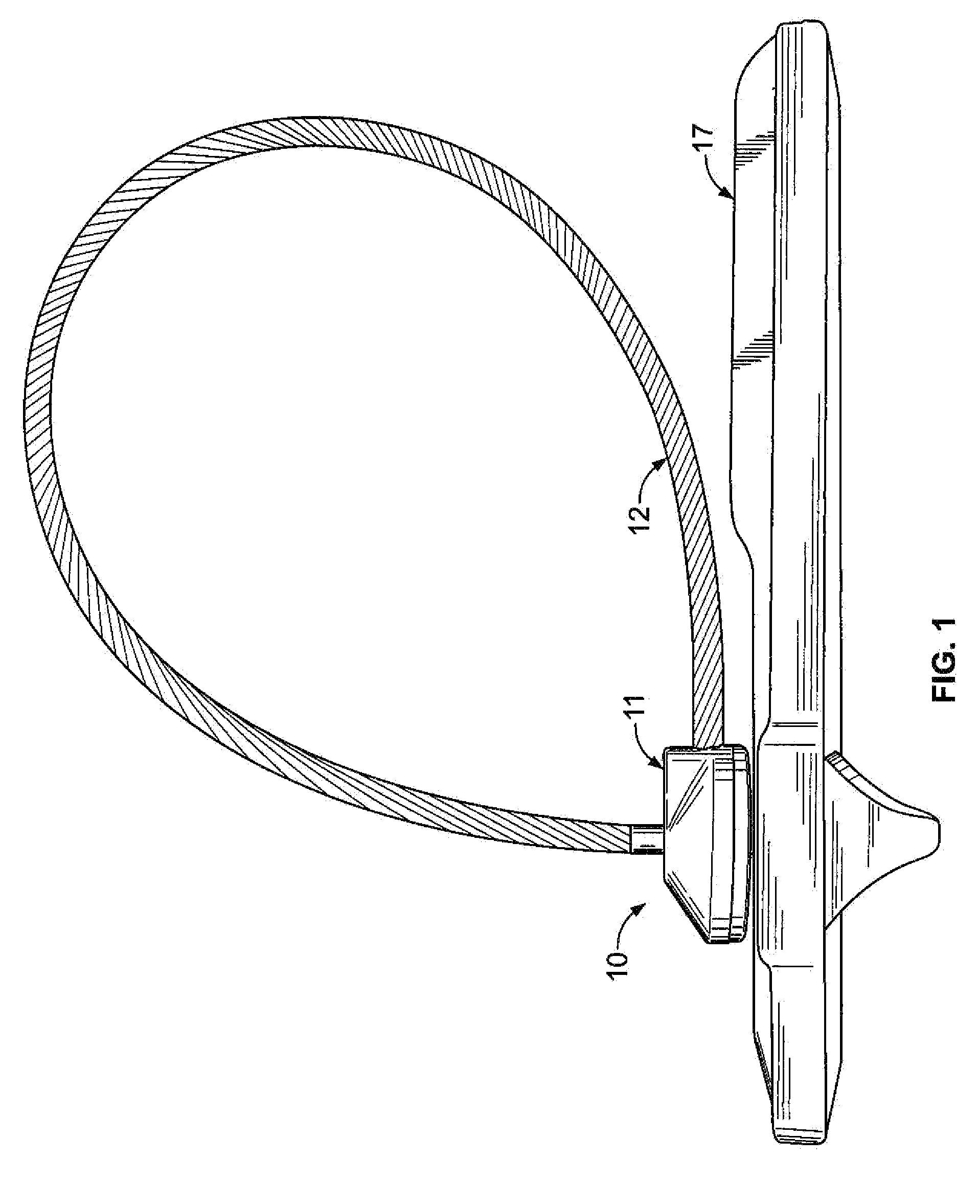
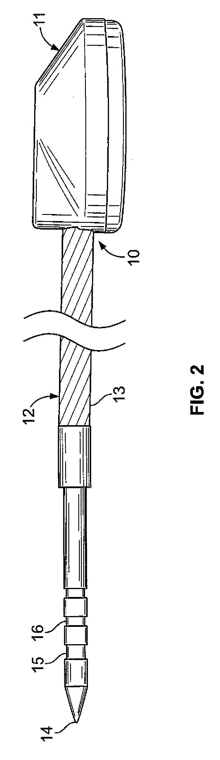
[0015]Referring to FIGS. 1 and 2, in a preferred embodiment 10 of the present invention, the combination lanyard 12 and base 11 of the present invention is comprised of an elongated lanyard 12 having a rectangular mountable end (not shown), a plastic covered wire central portion 13 and a pointed tip 14 at its opposing end with annular indents 15-16 adjacent the pointed tip 14 for being captured in the mounting aperture or hole (not shown) of an electronic article surveillance (EAS) tag 17.

[0016]Referring to FIGS. 3, 4 and 8, in the present preferred embodiment, the disk 11 portion of the invention includes a generally cylindrical base member 20 having a flat plain bottom 21 with an aperture 22 centrally perpendicularly therethrough. Adjacent the central aperture toward one part of the periphery is a female socket 23 shaped to receive the preferably generally rectangular, but also may be cylindrical, mounting end of the lanyard 12.

[0017]Referring to FIGS. 5, 6 and 7 cover 25 for the ...


PUM


Abstract

A mounting disk, lanyard and distal tip are formed as a unitary member and may be utilized with a plurality of differing EAS tags to provide effective theft protection devices.

Description

[0001]This application claims priority of Provisional Application 61 / 610593 filed Mar. 14, 2012, the contents of which are incorporated by reference, to the extent allowed by law.BACKGROUND OF THE INVENTION[0002]Retail stores utilize electronic article surveillance (EAS) tags, especially in connection with clothing, to prevent theft of such items. A tag will generally be a rectangular structure on the order of ⅝ inch in width and 1-½ inch in length with varying thickness, including a flat top side having a pin receiving aperture therein. For clothing and other fabric material items, a pin member, having a circular disk shaped top and a pin extending perpendicularly from the center thereof, is positioned through the fabric and into the aperture or hole in the tag to maintain the EAS structure on a consumer item to be sold. FIG. 3 of U.S. Pat. No. 7,084,766 discloses such a circular disk with pin extending therefrom that is meant to be positioned in the aperture or hole on the top of ...

Claims


Application Information

Patent Timeline
Patent Type & Authority Applications(United States)
IPC IPC(8): B65C7/00
CPCB65C7/001E05B73/0017Y10T24/3481Y10T24/3497G08B13/1445
Inventor ZIMMEL, LOUIS J.
Owner BEST SECURITY ACQUISITION LLC
Why Eureka
Try Eureka