System and method for inductively transferring ac power and self alignment between a vehicle and a recharging station

a self-alignement and inductive charging technology, applied in the direction of charging stations, electric vehicle charging technology, transportation and packaging, etc., can solve the problem that gapped transformers are generally less efficient for similarly sized and configured transformers, and achieve the effect of reducing induced noise and increasing the efficiency of gapped transformers

Active Publication Date: 2013-09-26
PLUGLESS POWER INC
View PDF3 Cites 14 Cited by
  • Summary
  • Abstract
  • Description
  • Claims
  • Application Information

AI Technical Summary

Benefits of technology

[0013]It is therefore a general aspect of the invention to provide a system and method for reducing induced noise, increasing the efficiency of a gapped transformer used in inductive charging, and a self-aligning proximity recharging station that will obviate or minimize problems of the type previously described.
[0014]According to a primary object of the invention, the apparatus for charging a battery in a vehicle includes a fixture having an interface plate which is movable in a number of directions. The gapped transformer includes a primary coil mounted on the interface plate and secondary coil mounted on the vehicle. A displacement mechanism is connected with the interface plate to position the primary coil proximate to the secondary coil to maximize the inductive transfer of power from the primary coil to the secondary coil which is used to charge the battery.
[0016]In a preferred embodiment, the interface plate is positioned relative to the vehicle by wireless communication system. The transformer includes control modules connected with the primary and second coils, with each module including a wireless communication device. When the vehicle is parked adjacent to the fixture, a low level of AC current is supplied to the primary coil to induce an AC current in the secondary coil. The level of the induced current in the secondary coil is transmitted to the control module connected with the primary coil. The control module activates the displacement mechanism to move the interface plate laterally, longitudinally, and vertically to position the primary coil proximate to the secondary coil in a position to maximize the inductive transfer of power. Once properly positioned, the level of AC current delivered to the primary coil is maximized to inductively transfer the current to the secondary coil where it is delivered to a charger to charge the vehicle batter.

Problems solved by technology

Gapped transformers generally are less efficient for similarly sized and configured transformers than non-gapped transformers which are manufactured as one continuous iron core.

Method used


Image

  • System and method for inductively transferring ac power and self alignment between a vehicle and a recharging station
  • System and method for inductively transferring ac power and self alignment between a vehicle and a recharging station
  • System and method for inductively transferring ac power and self alignment between a vehicle and a recharging station

Examples


Embodiment Construction

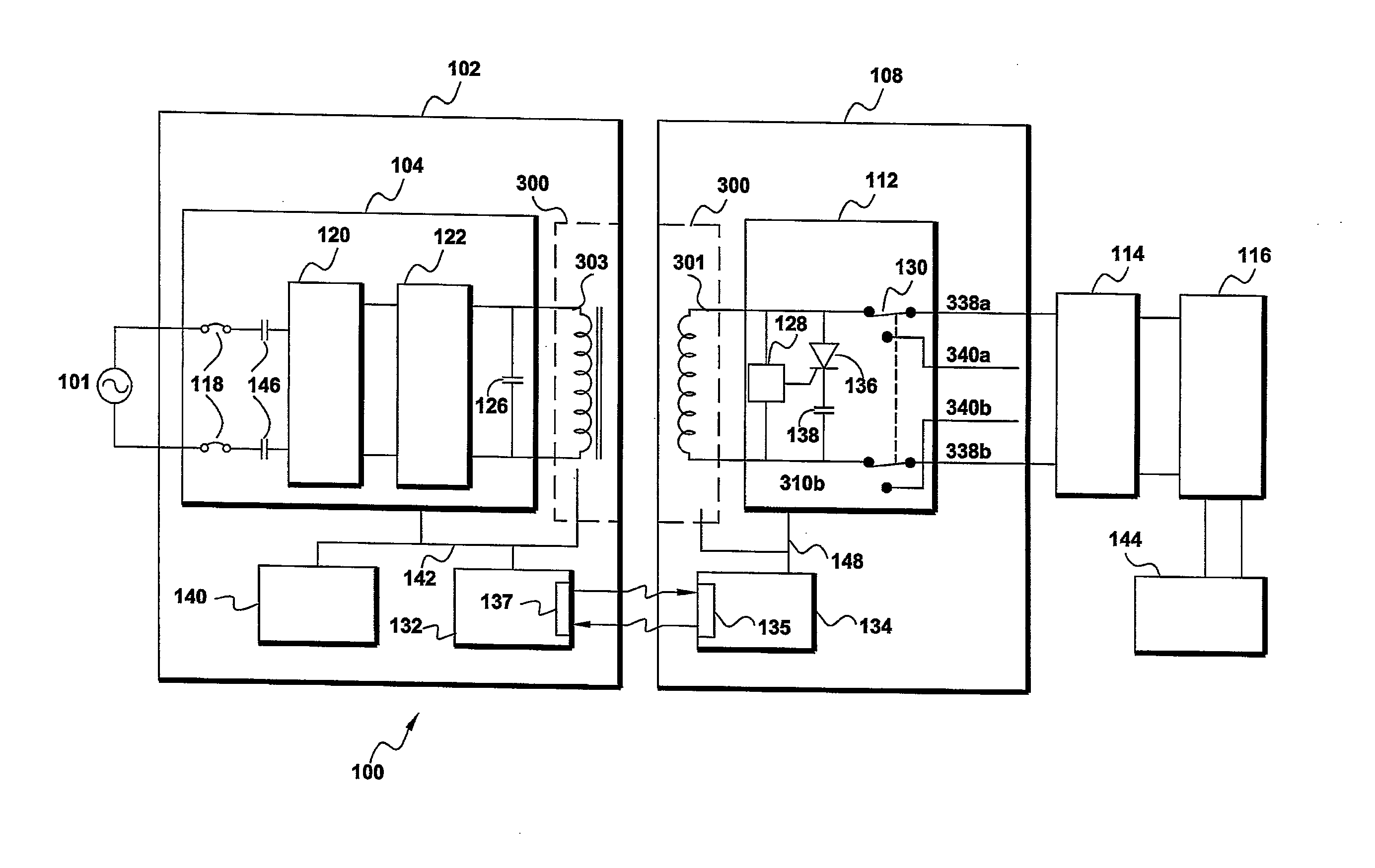
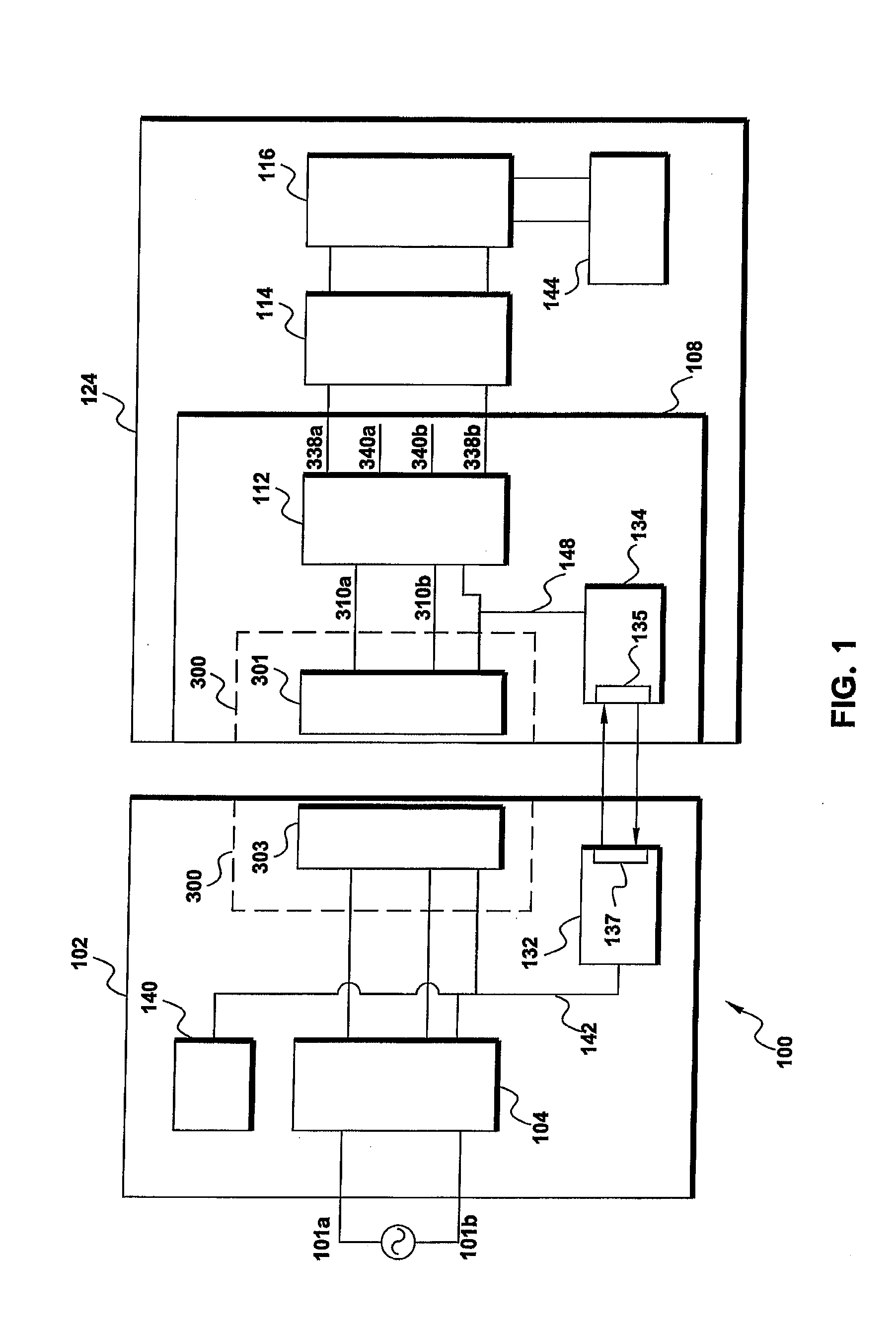
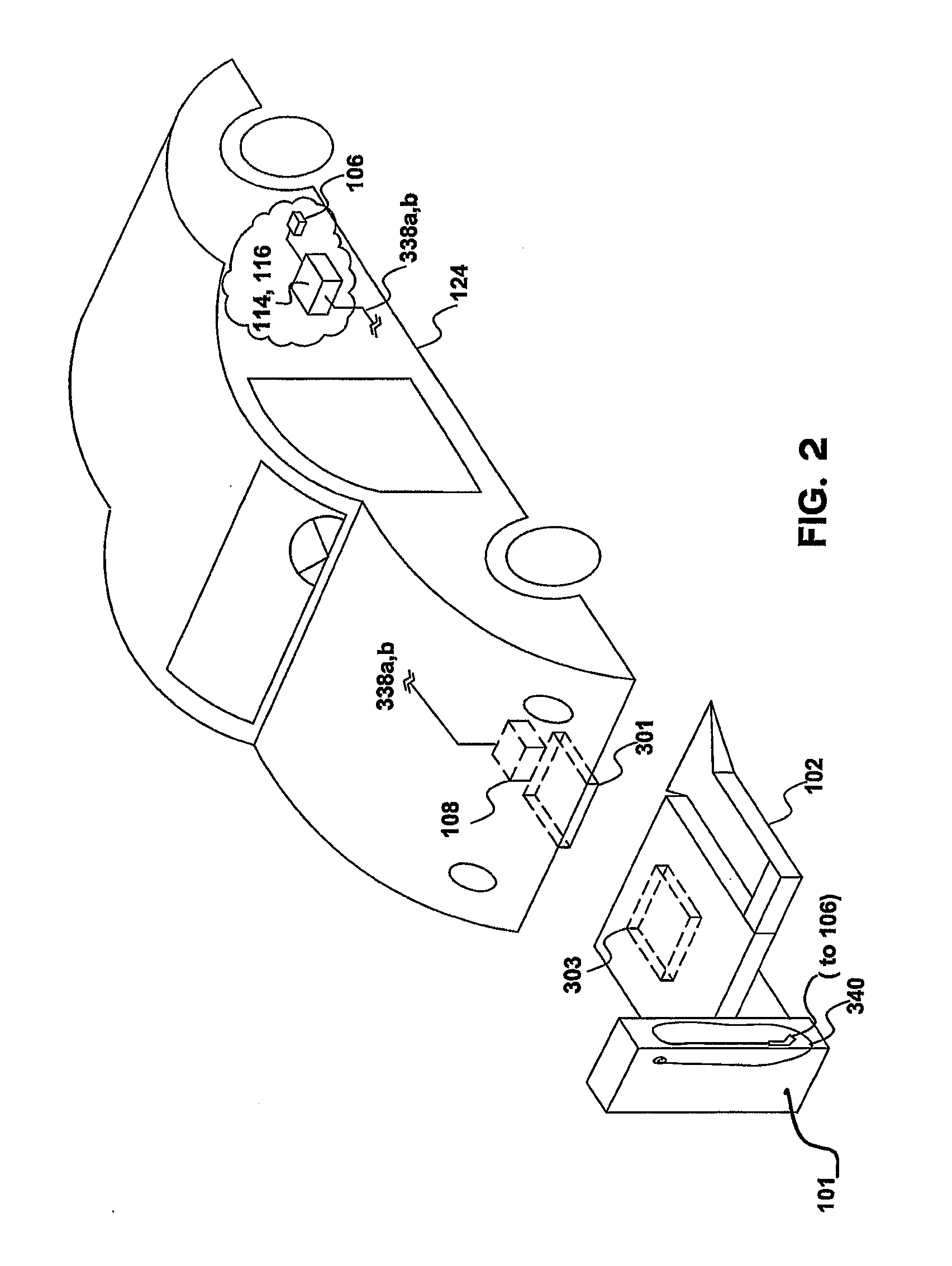
[0053]The self-aligning AC power transfer system (PTS) 100 according to the invention will initially be described with reference to FIG. 1 The system 100 includes a floor mounting station (FMS) 102 and a vehicle unit 108. Floor mounting station 102 includes a station electronic power transfer control unit (station control unit) 104, a station computer control and communications module 132, station unit indicators 140, and a station induction coil 303 which is part of an inductive, low noise, high efficiency AC power transfer system 300. Vehicle unit 108, which is mounted to and within a vehicle 124, includes a vehicle induction coil 301 (also part of the inductive low noise, high efficiency AC power transfer system 300), a vehicle electronic power transfer control unit (vehicle control unit) 112, and a vehicle computer control and communications module 134. Further shown in FIG. 1 as part of vehicle 124 are a charger 114, a battery 116, and an electrical engine 144. The floor mounti...


PUM

PropertyMeasurementUnit
frequencyaaaaaaaaaa
frequencyaaaaaaaaaa
frequencyaaaaaaaaaa

Abstract

A method and apparatus for hands free inductive charging of batteries for an electric vehicle is characterized by the use of a transformer having a primary coil connected with a charging station and a secondary coil connected with a vehicle. More particularly, the when the vehicle is parked adjacent to the charging station, the primary coil is displaced via a self alignment mechanism to position the primary coil adjacent to the secondary coil to maximize the inductive transfer of charging current to the secondary coil. The self alignment mechanism preferably utilizes feedback signals from the secondary coil to automatically displace the primary coil in three directions to position the primary coil for maximum efficiency of the transformer.

Description

[0001]This application claims the benefit of U.S. provisional patent application No. 61 / 308,099 filed Feb. 25, 2010.BACKGROUND OF THE INVENTION[0002]It is now well established that our nation, and many other nations, face serious environmental and fuel supply problems with internal combustion engines. Most internal combustion engines run on either gasoline or diesel fuels, both of which are petroleum products. As is well known, the world's oil supply is generally found far beneath the planet's surface, and in only a few specific locations. Enormous amounts of infrastructure and significant costs are involved in finding, extracting, and processing the oil into gasoline and diesel fuels, and further significant costs are incurred in the storage, transportation, and sale of the finished gasoline and diesel fuel products.[0003]It is well established that there is only a finite supply of petroleum in our world, and further that the byproducts of combustion, among them carbon monoxide (CO...

Claims


Application Information

Patent Timeline
Patent Type & Authority Applications(United States)
IPC IPC(8): H02J7/02
CPCH01F38/14H02J7/025Y02T90/122B60L11/182B60L11/1829Y10T29/4902Y02T90/125Y02T90/12Y02T90/14Y02T90/121Y02T10/7005Y02T10/7072B60L53/38B60L53/122B60L53/126H02J50/10H02J7/0044Y02T10/70H02J50/90
Inventor PAPARO, VINCENZO I.ATKINS, ROBERT
Owner PLUGLESS POWER INC
Why Eureka
Try Eureka