
Standoff adaptor for push pin

a technology of standoff adaptor and push pin, which is applied in the field of standoffs, can solve the problems of affecting the market competitiveness of art galleries or retail environments, the item to be mounted must be lightweight, and the price of such standoffs is relatively high

Active Publication Date: 2013-10-10
ACCURATE MFGD PRODS GROUP
View PDF25 Cites 5 Cited by
  • Summary
  • Abstract
  • Description
  • Claims
  • Application Information

AI Technical Summary

Benefits of technology

This patent describes a new and improved fastener for securing an item to a wall. It includes a spacer that can be attached to a push pin and a head that can be adjusted to securely hold an item in place. This invention is easier to use and more efficient than previous methods, making it easier to attach items to walls.

Problems solved by technology

One limitation is that the item to be mounted must be lightweight since the item located between the push pin main body and the wall or hung on the push pin provides a downward force on the small diameter pin inserted into the wall.
Another limitation is that the item to be mounted to the wall may be positioned immediately adjacent the wall and does not standoff outwardly from the wall.
Since the art is rotated often in galleries, these problems are magnified.
The price of such standoffs is relatively high for art galleries or in a retail environment.

Method used


Image

  • Standoff adaptor for push pin
  • Standoff adaptor for push pin
  • Standoff adaptor for push pin

Examples


Embodiment Construction

[0022]For the purposes of promoting an understanding of the principles of the invention, reference will now be made to the embodiment illustrated in the drawings and specific language will be used to describe the same. It will nevertheless be understood that no limitation of the scope of the invention is thereby intended, such alterations and further modifications in the illustrated device, and such further applications of the principles of the invention as illustrated therein being contemplated as would normally occur to one skilled in the art to which the invention relates.

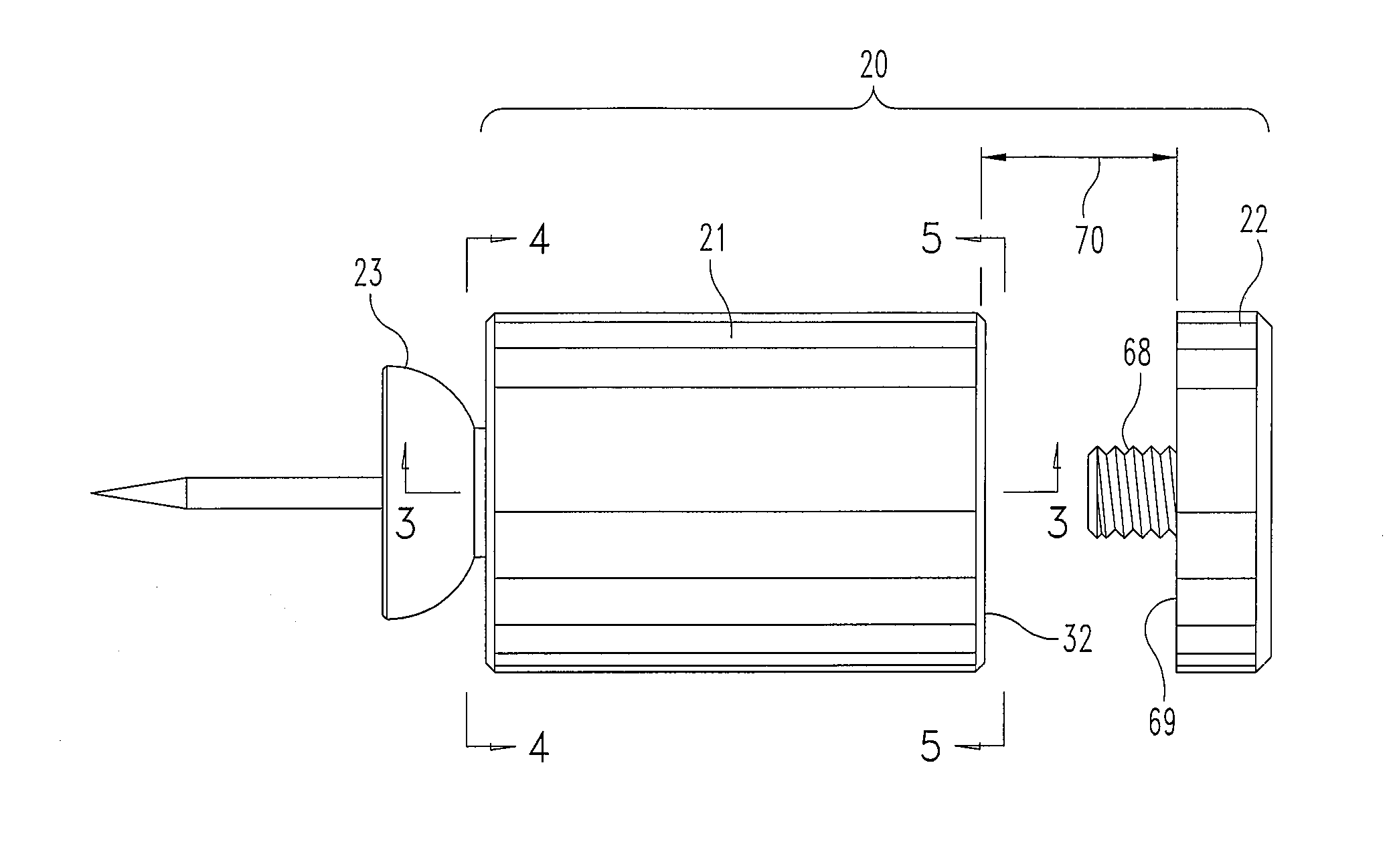
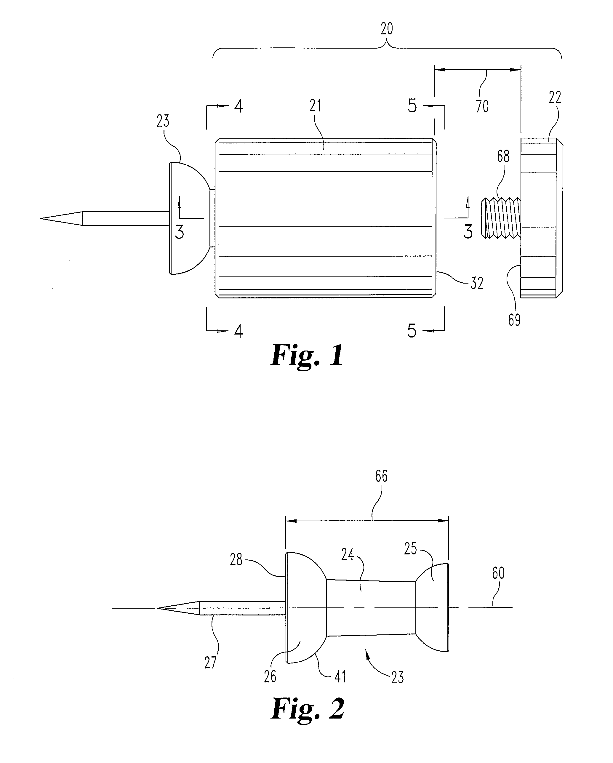
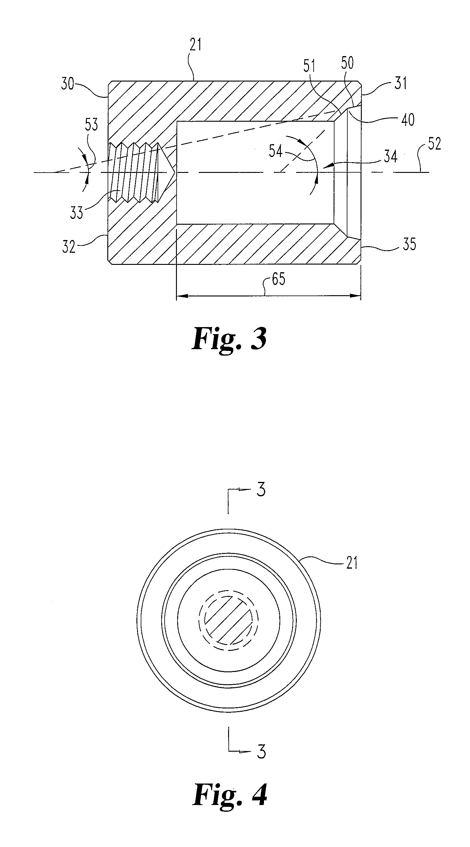
[0023]FIG. 1 shows an adaptor being assembled to a push pin. The adaptor 20 includes a main body 21 having a head 22 threadedly mountable thereto. The main body 21 of the adaptor forms a spacer and has a hole at the opposite end of the head into which a push pin 23 may be inserted.

[0024]A commercially available push pin 23 is shown in FIG. 2 and has a main body with opposite enlarged heads 25 and 26 with the por...


PUM

PropertyMeasurementUnit
thicknessaaaaaaaaaa
thicknessaaaaaaaaaa
distanceaaaaaaaaaa

Abstract

A standoff adaptor for a push pin. A spacer has a hole formed in one end to complementarily receive a push pin with the pin of the push pin extending outwardly therefrom. A head is threadedly mounted to the opposite end of the spacer and may be adjusted to tightly grip an item between a spacer and head.

Description

BACKGROUND OF THE INVENTION[0001]1. Field of the Invention[0002]The present invention relates generally to the field of standoffs used to mount an item in spaced relationship to a wall.[0003]2. Description of the Prior Art[0004]Push pins are used to mount notes, signs and variety of items to a bulletin board, wall or other supporting structure. Push pins come in a variety of shapes and configurations; however, they include a main body, typically plastic, having a metal pin mounted thereto and extending outwardly to pierce the wall upon which the main body of the push pin is to be mounted. The advantage of the push pin is that only a tiny hole is created in the wall for the mounting of the push pin. One limitation is that the item to be mounted must be lightweight since the item located between the push pin main body and the wall or hung on the push pin provides a downward force on the small diameter pin inserted into the wall. Another limitation is that the item to be mounted to the...

Claims


Application Information

Patent Timeline
Patent Type & Authority Applications(United States)
IPC IPC(8): F16B2/06B23P11/00F16B15/00
CPCB43M15/00Y10T24/3467Y10T24/44026Y10T29/49948Y10T29/4995Y10T29/49947
Inventor GOLDBERG, MATTAGNELLO, LAWRENCE S.
Owner ACCURATE MFGD PRODS GROUP
Learn More