Cup sleeve

a technology for sleeve and cup, which is applied in the field of auxiliary products, can solve the problems of loss of the function of the cup sleeve protecting people from being heated, easy sliding of the airflow layer, and difficult to hold, etc., and achieves the effects of convenient removal, simple and environmental protection, and increased inner tensile for

Inactive Publication Date: 2013-10-10
CHINA USA DIRECT SOURCE
View PDF4 Cites 2 Cited by
  • Summary
  • Abstract
  • Description
  • Claims
  • Application Information

AI Technical Summary

Benefits of technology

The present invention is a heat-isolating cup sleeve that is easy to use and doesn't require any additional material. The cup sleeve is designed to fit snugly around a cup and is secured in place using a die-cutting part that folds inwards, creating a tight grip. This prevents the cup sleeve from sliding off the cup when the beverage is cool. The cup sleeve is simple, easy to use and environmentally friendly.

Problems solved by technology

If wanting to drink a cup of hot beverage which is just taken by hands, the cup is very hot and difficult to be held.
However, a problem of the conventional cup sleeve is that, the cup sleeve for isolating from the heat is prone to slide down from an original fit and proper location of the cup to a placing plane when the cup with the cup sleeve is placed on the placing plane, such as dining table, work table or other plane surfaces.
Thus, the cup sleeve losses the function for protecting people from being heated by the cup filled with the hot beverage.
When the hot beverage is poured into the cup, the material between the cup and the cup sleeve which should be closely contacted with each other, are thermal-expanded non-uniformly, thus an airflow layer is generated therebetween, and the airflow layer is prone to slide the cup sleeve down from the original-designed proper location.
Therefore, when using the conventional cup sleeve, it may not only continuously repeat some actions, but also lean the cup and spill the hot beverage to heat the user himself, or spill the hot beverage to pollute or damage peripheral books, documents, and / or clothing, in the process of pushing the cup sleeve to the original location of the cup which is filled with the hot beverage.
This is a very severe problem for the user.
In addition, if considering from the business factors, if the user always looks at the cup and continuously adjust the cup and the cup sleeve when carrying on the business conversation or on some social occasions, it is very embarrassing and unpleasant.
However, a new problem is generated, that is, when the beverage is cooled, the cup sleeve is difficult to be taken out from the cup.
Furthermore, if not needing the cup sleeve, the user still needs to take the cup with the cup sleeve, and throw away the cup with the cup sleeve after drink the beverage completely.
Therefore, the cup sleeve with the viscous glue is difficult to be taken out, and it is disadvantage to recovery and environmental.
It not only increases the cost, but also is not environmental.
Therefore, the cup sleeve is difficult to slide from the cup.

Method used


Image

  • Cup sleeve
  • Cup sleeve
  • Cup sleeve

Examples


first embodiment

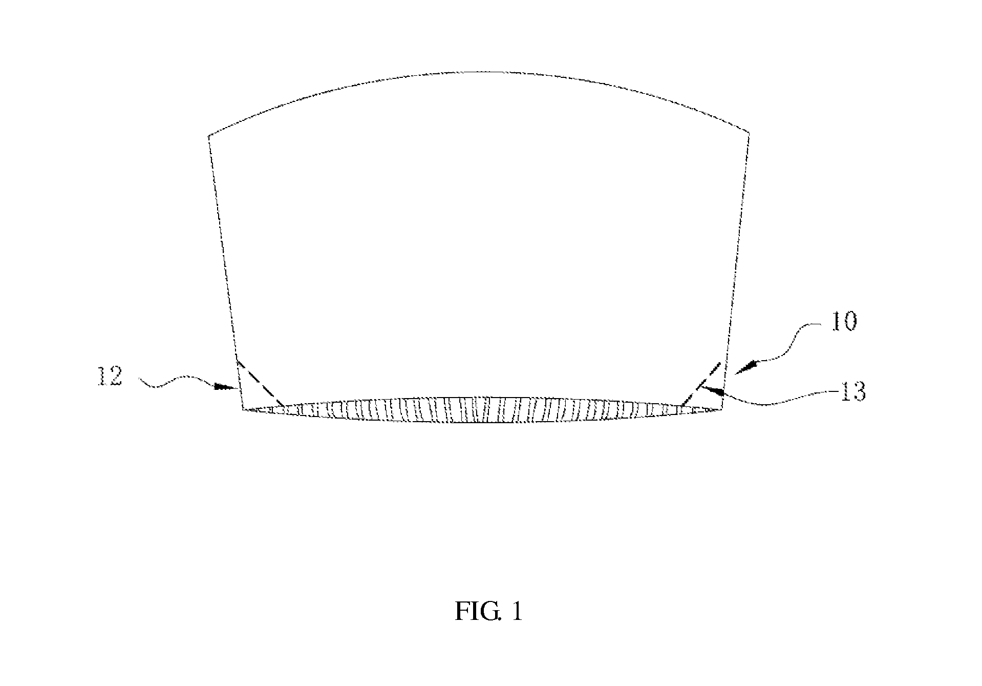
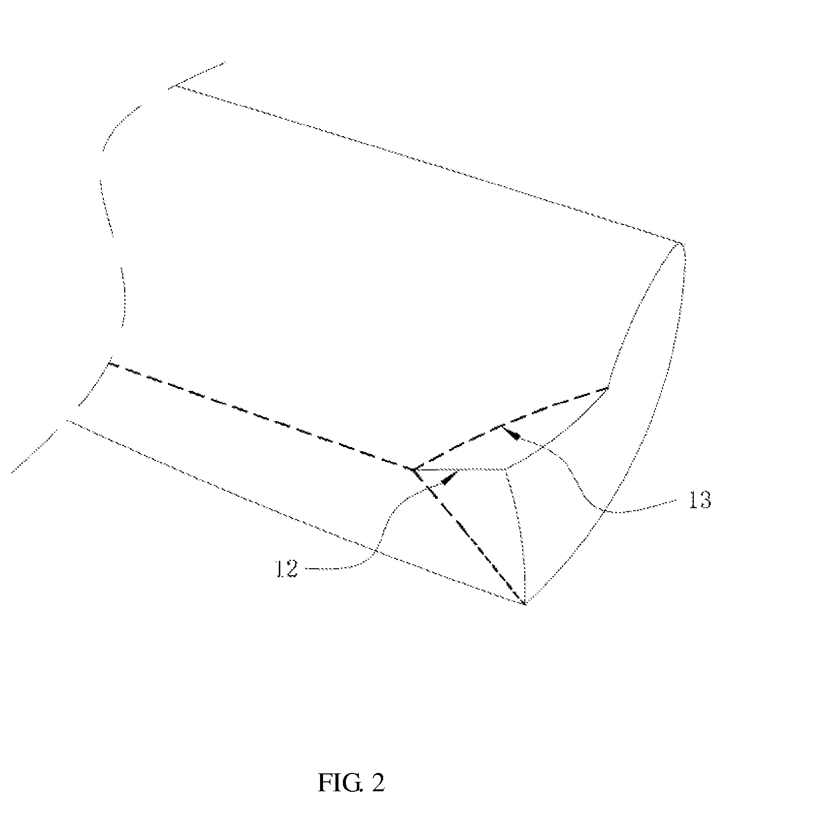
[0024]The fixer may be achieved by two following embodiments which have same concepts but are different little with each other. FIG. 1 is a structure view of a cup sleeve in accordance with the present invention, FIG. 2 is a schematic view for showing a folding mode of a fixer 10 of the cup sleeve as shown in FIG. 1, and FIG. 3 is a using-state view of the cup sleeve as shown in FIG. 1. As shown in FIGS. 1-3, the fixer 10 is formed by die cutting two delta-shaped regions at two ends of the bottom of the cup sleeve and inward folding the delta-shaped regions. Each of the delta-shaped regions has a severable part 12 in the middle of each delta-shaped region. The severable part 12 is pushed inwards by forces to be divided into two independent parts because the severable part 12 bears the overlarge pushing forces. The two independent parts are folded inwards along two corresponding folded parts 13, and the two folded parts 13 are held by hands. Then a cup may slid into the cup sleeve, a...

second embodiment

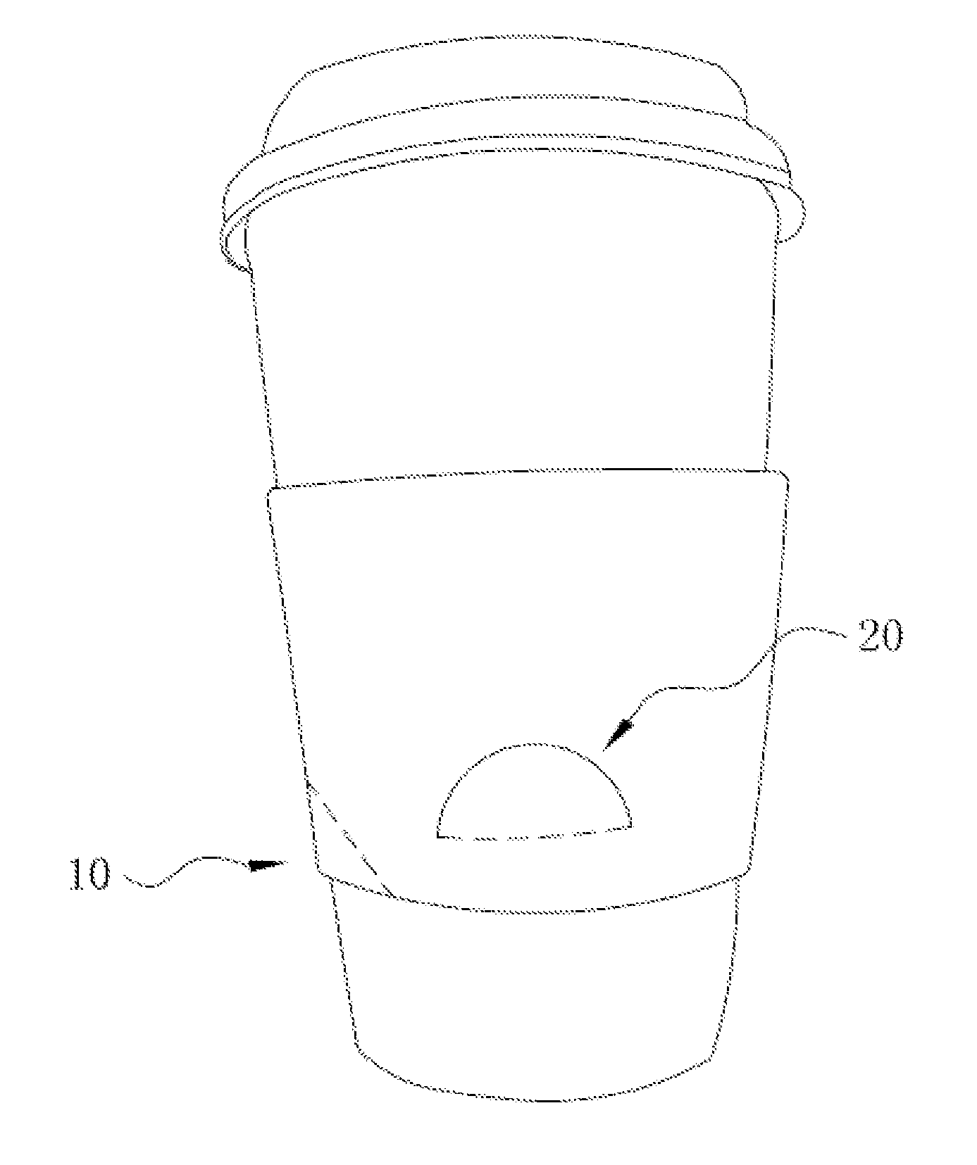
[0025]FIG. 4 is a structure view of a cup sleeve in accordance with the present invention, FIG. 5 is a schematic view for showing a folding mode of a fixer 20 of the cup sleeve as shown in FIG. 4, and FIG. 6 is a using-state view of the cup sleeve as shown in FIG. 4. As shown in FIGS. 4-6, the fixer 20 is formed by disposing a hole-shaped die-cutting part on the main body. The hole-shaped die-cutting part comprises a folded part 23 and a severable part 22 which may be disconnected from the folded part 23 by pushing inwards. The hole-shaped die-cutting part may be rectangle-shaped, sector-shaped, delta-shaped, etc. Preferably, the hole-shaped die-cutting part is half round-shaped and comprises an arc portion and a straight-line portion. The arc portion is upward and used as the severable part 22, and the straight-line portion is downward and used as the folded part 23. The hole-shaped die-cutting part may be disposed at anywhere of the cup sleeve. Preferably, the hole-shaped die-cutt...


PUM


Abstract

The present invention relates to a heat-isolating cup sleeve, which comprises a main body and at least one fixer disposed on the main body and able to be folded inwards to insert between a cup and the cup sleeve. The present invention employs a die-cutting part and folds inwards the die-cutting part to form the fixer similar to a wedge, so as to increase inner tensile forces of the cup sleeve sleeving a cup so that the cup sleeve is in a tensioning state and closely attaches with the cup. Therefore, the cup sleeve is difficult to slide from the cup. When the beverage is cooled, the cup sleeve is conveniently taken down from the cup, and is simple and environmental.

Description

BACKGROUND[0001]1. Technical Field[0002]The present invention relates to living supplies, and more particularly, to an auxiliary product for holding a cup which is used to fill high-temperature or hot beverages.[0003]2. Description of Related Arts[0004]Beverage shops and / or coffee shops for selling beverages and coffee, usually use paper-cups for customers packing with hot beverages. Generally, walls of the paper-cups are relatively thin and the heat-insulation effect is common. If wanting to drink a cup of hot beverage which is just taken by hands, the cup is very hot and difficult to be held. A common solution is attaching a cup sleeve when selling the hot beverage, and the cup sleeve is made of thin corrugated paper and sleeved in the middle of a cup to be isolated from heat and be conveniently held by hands. However, a problem of the conventional cup sleeve is that, the cup sleeve for isolating from the heat is prone to slide down from an original fit and proper location of the ...

Claims


Application Information

Patent Timeline
IPC IPC(8): B65D81/38
CPCB65D81/3876B65D3/00B65D81/00B65D81/3865
Inventor PAPANIKOLAOU, EMMANOUIL
Owner CHINA USA DIRECT SOURCE
Why Eureka
Try Eureka