
Touch display device and method for conditionally varying display area

a display device and display area technology, applied in the field of electronic devices with conditionally variable display area, can solve the problems of high display cost and difficult production using current technology, and achieve the effects of enhancing user's reading experience, light and easy use, and touching display

Inactive Publication Date: 2013-10-17
WISTRON CORP
View PDF7 Cites 41 Cited by
  • Summary
  • Abstract
  • Description
  • Claims
  • Application Information

AI Technical Summary

Benefits of technology

The patent describes a touch display device with a feature that prevents accidental touches when the user is holding the device with their hand. This feature allows for reduced-border designs, making the device easier to use and providing better user experience.

Problems solved by technology

However, such a display has higher cost and is still difficult to produce using current technology.

Method used


Image

  • Touch display device and method for conditionally varying display area
  • Touch display device and method for conditionally varying display area
  • Touch display device and method for conditionally varying display area

Examples


first embodiment

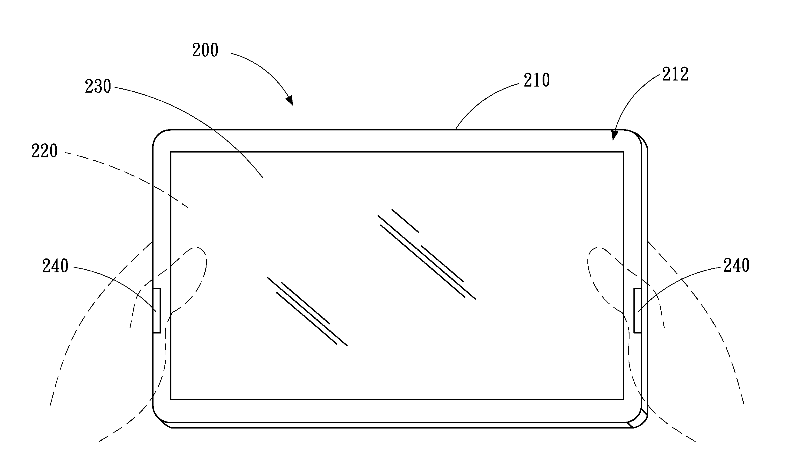
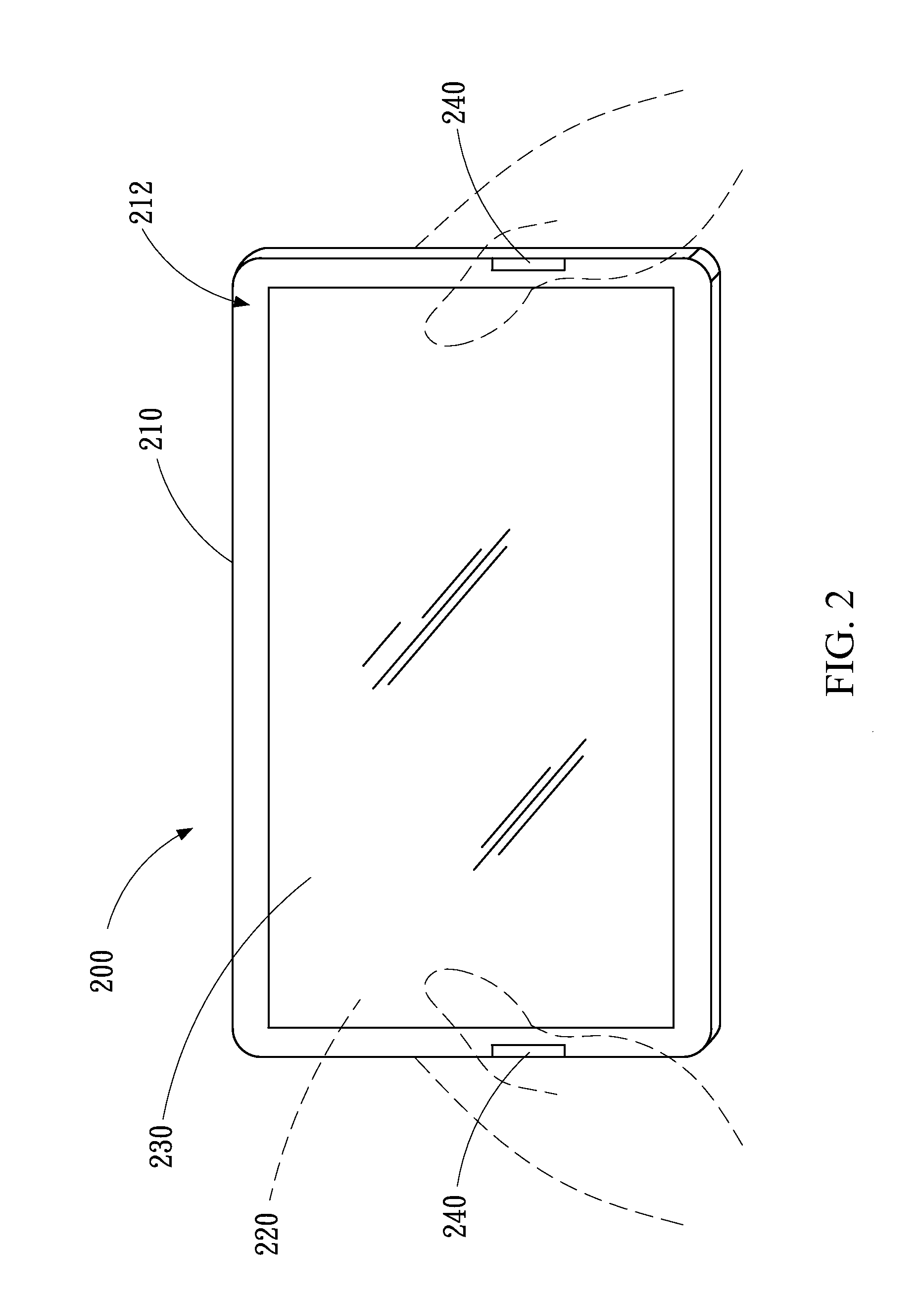
[0030]Please refer to FIG. 2 and FIG. 3, in which a touch display device 200 is disclosed to vary a sensing area based on user's operation methods, and further to adjust a display area. A practical example for the touch display device 200 is tablet computer, without excluding any other type of the touch display device 200.

[0031]As shown in FIGS. 2, 3 and 4, the touch display device 200 includes a housing 210, a display panel 220, a touch panel 230, a trigger module 240 and a control module 250.

[0032]As shown in FIGS. 2 and 4, the housing 210 has a border 212. The display panel 220 and the touch panel 230 are installed within the border 212 of the housing 210. The touch panel 230 is combined on the display panel 220, which may be possibly realized by attaching the touch panel 230 onto the display panel 220, or embedding touch control components inside the display panel 220 to form an in-cell touch panel or an embedded optical touch panel. The trigger module 240 is disposed on the bo...

third embodiment

[0046]Please refer to FIGS. 9 and 10, which disclose a touch display device 200 according to a The touch display device 200 includes a housing 210, a display panel 220, a touch panel 230, a trigger module 240a, and a control module 250.

[0047]As shown in FIG. 10, the trigger module 240a is a functional module including the touch panel 230, the control module 250 and an adjusting code 260. When the touch display device 200 is boosted, the control module 250 loads the adjusting code 260 from a storage unit and executes. Next, the control module 250 receives the touch instruction T output by the touch panel 230 and determines the touch position corresponding to the touch instruction T. When the object 300 (e.g. the user's hand), contacts the touch panel 230, the touch position corresponding to the touch instruction T generated by the touch panel 230 is located in a designated block. The designated block is for example a specific partial position in the blank region, or corresponds to a...


PUM


Abstract

A touch display device includes a display panel, a touch panel, a trigger module and a control module. The touch panel has a sensing area equivalent to the maximum display area of the display panel. The sensing area detects a touch event occurring thereon in order to generate a touch instruction. The control module executes the touch instruction and generates a display signal to drive the display panel to display images in the current display area which is not greater than the maximum display area. When the trigger module generates a trigger signal, the control module reduces the current display area to form a blank region in at least one side of the current display area. Accordingly, the touch event occurring on the blank region generates an invalid touch instruction.

Description

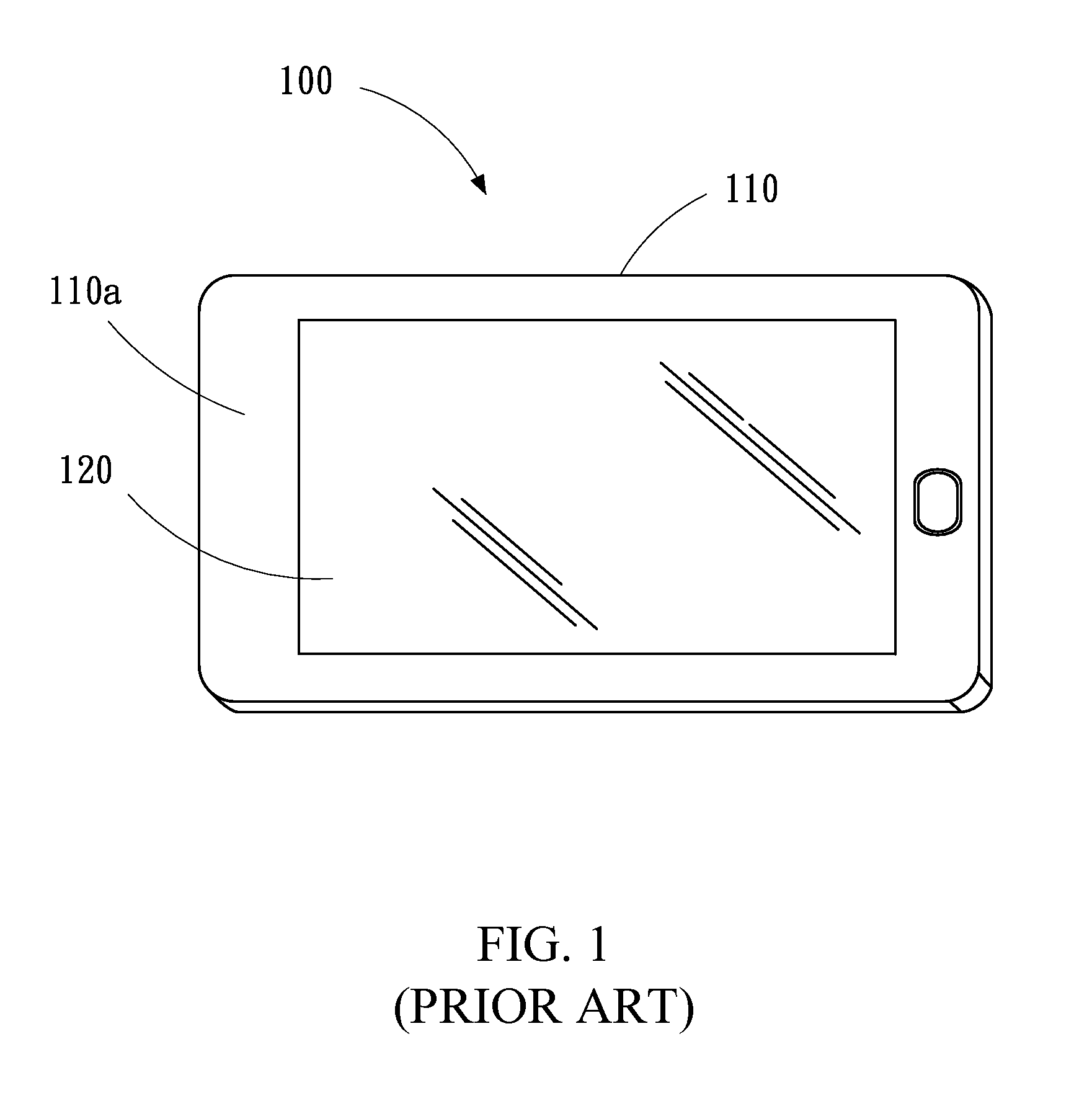
CROSS-REFERENCES TO RELATED APPLICATIONS[0001]This non-provisional application claims priority under 35 U.S.C. §119(a) on Patent Application No. 101112881 filed in Taiwan, R.O.C. on 2012 / 04 / 11, the entire contents of which are hereby incorporated by reference.BACKGROUND[0002]1. Technical Field[0003]The disclosure relates to touch operations of an electronic device, in particular to a touch display device and method for conditionally varying display area.[0004]2. Related Art[0005]Accompanying the development of information technology and the increase of internet coverage, touch display devices such as smartphones or tablet computers have become increasingly popular recently, and become significant interfaces for acquiring or exchanging information. This enables a user to freely browse multimedia information such as internet information or e-books, anytime and anywhere.[0006]FIG. 1 illustrates a conventional touch display device 100. A touch screen 120 is installed in a housing 110 on...

Claims


Application Information

Patent Timeline
Patent Type & Authority Applications(United States)
IPC IPC(8): G06F3/041
CPCG06F3/041G06F3/0488G06F2203/04803
Inventor TSAI, CHU-CHIACHANG, RANDY LU HUNG
Owner WISTRON CORP
Learn More