Prompt apparatus for an anesthesia machine and a corresponding anesthesia machine

a technology of anesthesia machine and corresponding anesthesia machine, which is applied in the field of medical devices, can solve problems such as not providing a timely signaling technology, and achieve the effect of reducing the cost of realization and increasing the security of using the anesthesia machin

Active Publication Date: 2014-05-29
GENERAL ELECTRIC CO
View PDF10 Cites 0 Cited by
  • Summary
  • Abstract
  • Description
  • Claims
  • Application Information

AI Technical Summary

Benefits of technology

[0019]Compared with the prior art, the signaling apparatus for an anesthesia machine and the corresponding anesthesia machine, as provided by embodiments of the present invention, have the following advantageous technical effects: increasing the security of using the anesthesia machine: since the signaling apparatus is capable of signaling to a user what gases at present are mixed into the final output gases, and is capable of signaling the user which gas outlet is available, misoperations that are caused for the reason that the user may be unaware of the above information, can be avoided; and having a lower cost of realization: corresponding information can be timely, intuitively and clearly signaled to the user without making excessive modifications or adding expensive parts to the existing anesthesia machines.

Problems solved by technology

However, the prior art including US Patent Application Publication No. 2010 / 0175695, does not provide a technical solution capable of timely signaling a user of an anesthesia machine what gases are mixed together currently, and which gas outlet is available.

Method used


Image

  • Prompt apparatus for an anesthesia machine and a corresponding anesthesia machine
  • Prompt apparatus for an anesthesia machine and a corresponding anesthesia machine
  • Prompt apparatus for an anesthesia machine and a corresponding anesthesia machine

Examples


Embodiment Construction

[0026]The present invention will be further illustrated below with reference to the drawings.

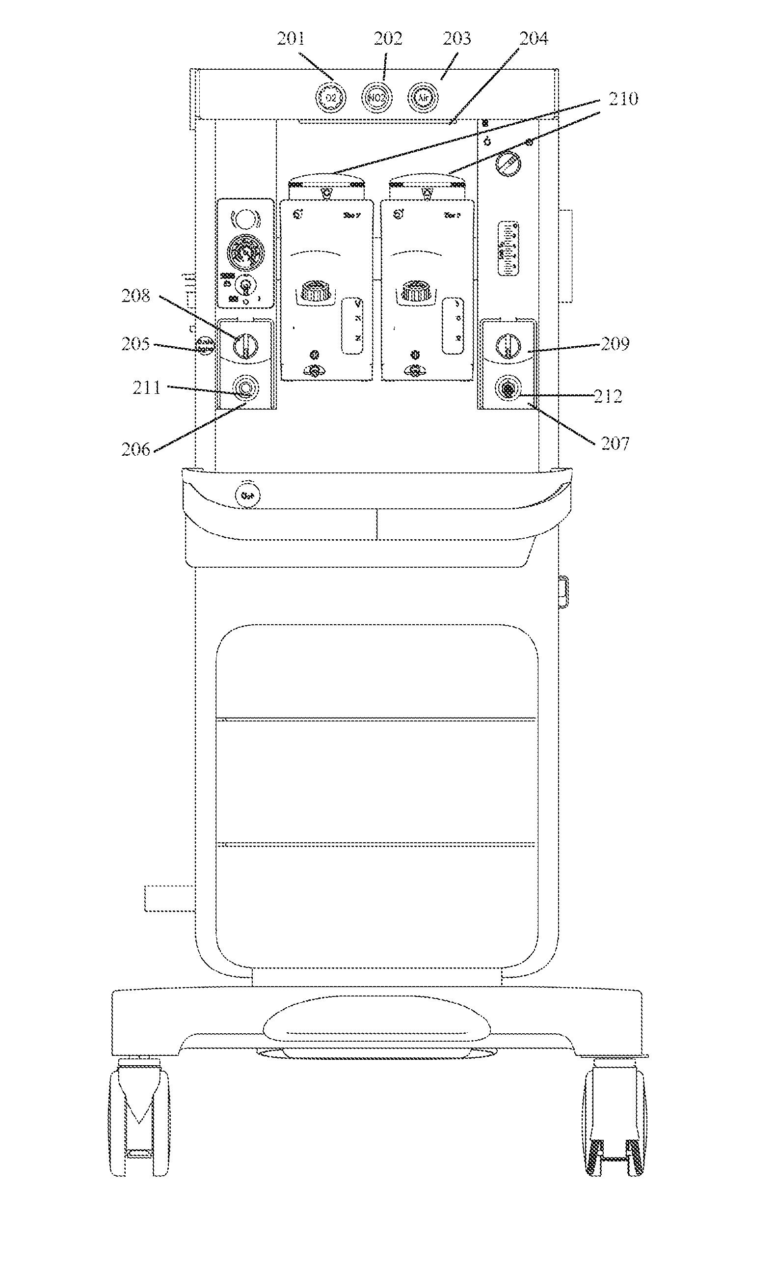
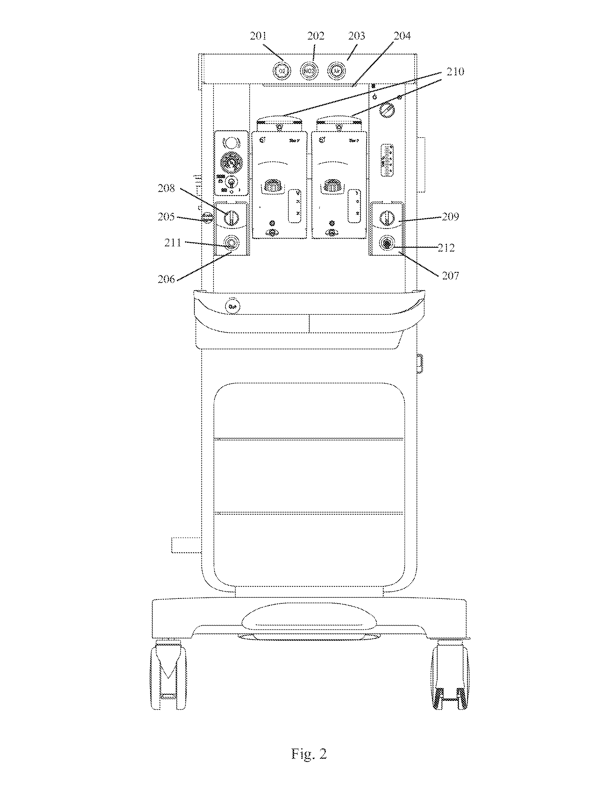
[0027]FIG. 2 shows an overall structure of the signaling apparatus for an anesthesia machine and the corresponding anesthesia machine, as proposed by an embodiment of the present invention.

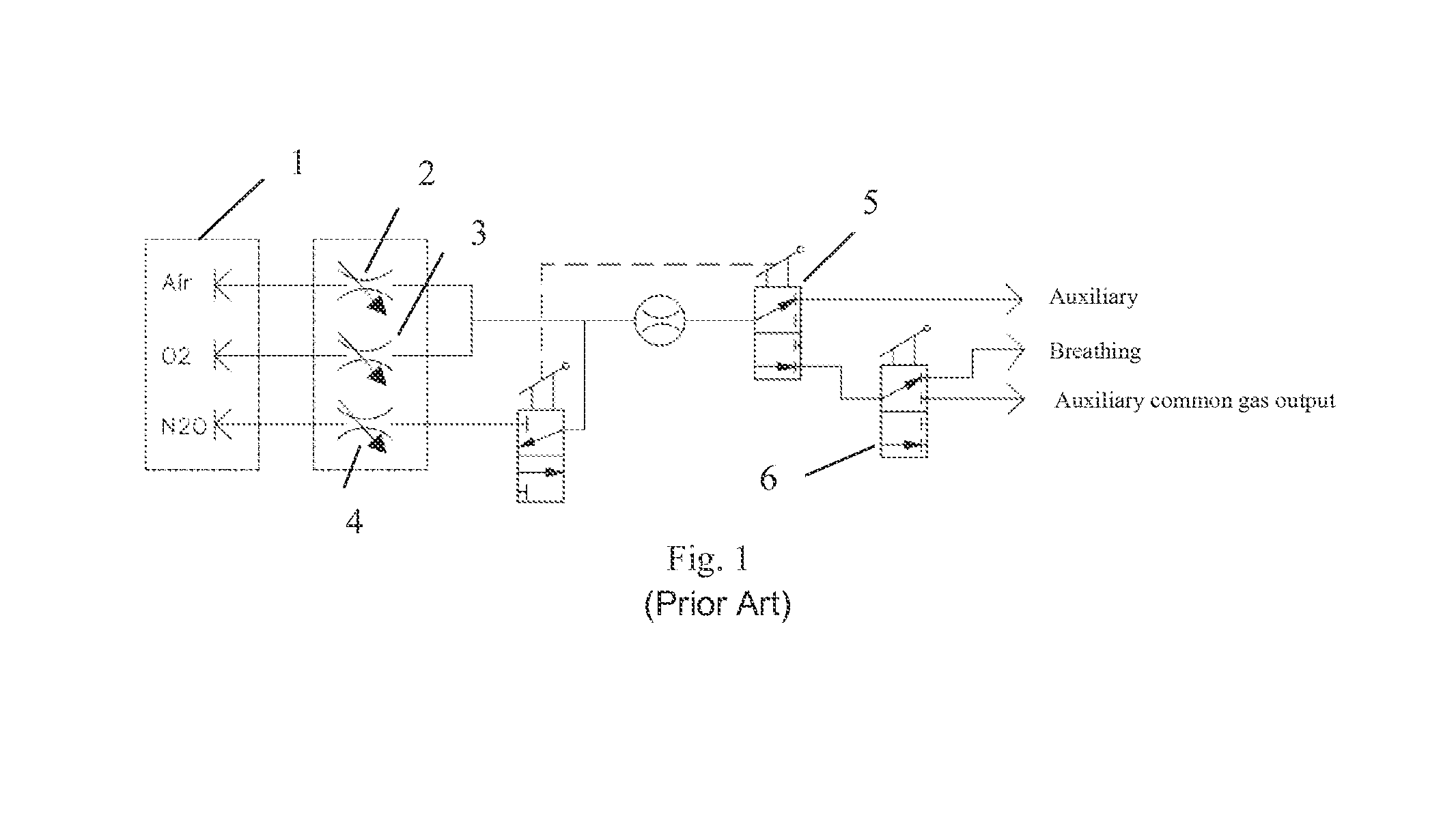
[0028]In FIG. 2, a first transfer switch 209 and a second transfer switch 208 constitute a user input sub-module; via the first transfer switch 209, a user can decide whether it is necessary to conduct auxiliary gas output, and via the second transfer switch 208, the user can decide whether it is necessary to conduct auxiliary common gas output. When both the transfer switches are turned to an “OFF” position, the anesthesia machine will conduct breathing circuit output. When both the transfer switches are turned to an “ON” position, the anesthesia machine will conduct auxiliary gas output. These two switches are not limited to mechanic switching valves, but can also be electronic switching valves.

[0029]In ...


PUM


Abstract

A signaling apparatus for an anesthesia machine, the signaling apparatus comprising an user input sub-module for receiving input information from an user, an available gas sub-module for signaling types of currently available gases according to information of the user input sub-module, and an available gas outlet sub-module for signaling currently available gas outlets according to information of the user input sub-module.

Description

TECHNICAL FIELD[0001]The present invention relates to the technical field of medical devices, in particular, the technical field of anesthesia machines.BACKGROUND OF THE INVENTION[0002]Anesthesia machines used in hospitals usually need to provide the following three different gas outlets, namely, auxiliary gas outlet, auxiliary common gas outlet, and breathing circuit gas outlet. At any moment, only one of the three outlets is in an available state. Hence, a doctor, at any moment, needs to clearly know which gas outlet is in an available state, to ensure that gases can be provided to a patient in the manner conceived by the doctor.[0003]The existing anesthesia machines usually adopt the structure as shown by FIG. 1 to allocate oxygen, air, and N2O as required by the doctor. That is, oxygen, air and N2O from high pressure equipment 1 are mixed via mechanic or electronic flow control valves 2, 3, 4 respectively. The mixed gases are output to gas outlets as required by the doctor via m...

Claims


Application Information

Patent Timeline
Patent Type & Authority Applications(United States)
IPC IPC(8): A61M16/00A61M16/12A61M16/20A61M16/10
CPCA61M16/0051A61M16/20A61M16/12A61M16/104A61M2202/0208A61M2202/0283A61M2205/583A61M2209/084A61M16/021
Inventor BEDUHN, DONALDYU, LINGJIEJIANG, GAOFENG
Owner GENERAL ELECTRIC CO
Why Eureka
Try Eureka