Engine testing apparatus, and engine testing method

a technology of engine testing and testing apparatus, which is applied in the direction of hydrodynamic testing, instruments, structural/machine measurement, etc., can solve the problems of inability to appropriately reproduce the rise of the engine rotation speed, the inability of the dynamometer to reproduce the load equivalent to that of a real vehicle, and the inability of the engine testing apparatus to appropriately reproduce the engine behavior in a real vehicle. achieve the effect of easily and appropriately reproducing the engine behavior

Active Publication Date: 2014-01-16
TOYOTA JIDOSHA KK +1
View PDF6 Cites 12 Cited by
  • Summary
  • Abstract
  • Description
  • Claims
  • Application Information

AI Technical Summary

Benefits of technology

[0008]An object of the present invention is to provide an engine testing apparatus and an engine testing method that easily and appropriately reproduce the engine behavior in a real vehicle when the engine rotation speed is rapidly changed at the time of starting the engine or changing the speed.

Problems solved by technology

Accordingly, when the engine rotation speed is rapidly changed at the time of starting the engine, the dynamometer cannot reproduce the loads equivalent to those of a real vehicle.
Therefore, as shown in FIG. 10, the engine testing apparatus cannot appropriately reproduce the rise of the engine rotation speed at the time of starting the engine in a real vehicle in the test.
However, the timing of the feedforward is not considered so that the engine testing apparatus may assist in the rise of the rotation at the time of starting the engine by the feedforward.
Therefore, in the engine testing apparatus, the engine behavior in a real vehicle may not be reproduced.
The creation of a map illustrating the relationship requires much time.

Method used


Image

  • Engine testing apparatus, and engine testing method
  • Engine testing apparatus, and engine testing method
  • Engine testing apparatus, and engine testing method

Examples


Embodiment Construction

[0021]Hereinafter, an engine testing apparatus and an engine testing method according to an embodiment of the present invention will be described in details with reference to FIGS. 1 to 8.

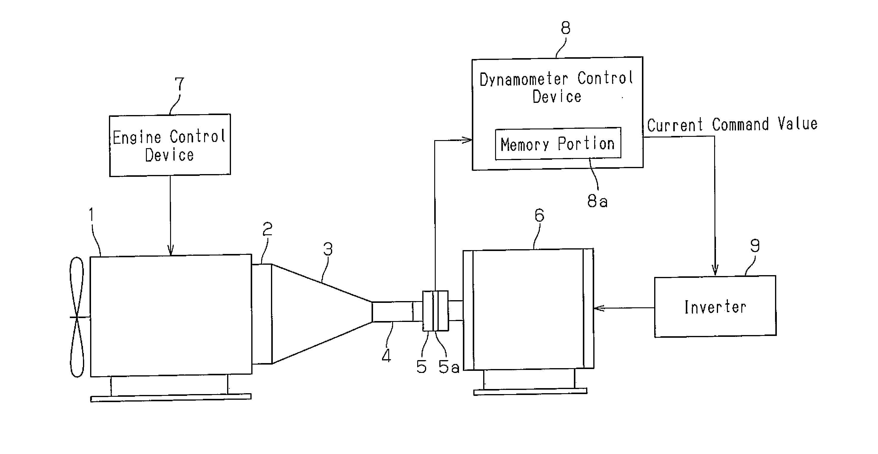
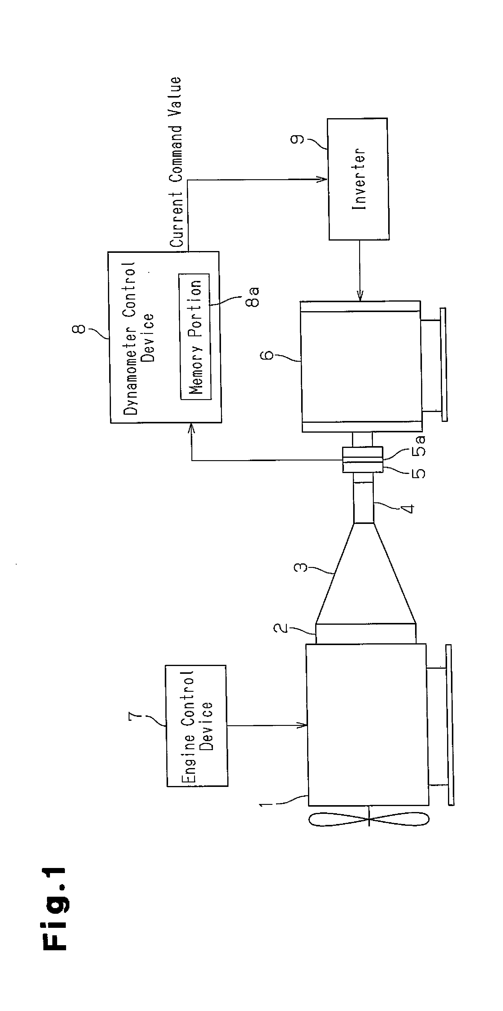
[0022]First, with reference to FIG. 1, the configuration of the engine testing apparatus according to the present embodiment will be described. As shown in FIG. 1, in the engine testing apparatus, an engine under test 1 is arranged such that it is connected to a manual transmission 3 via a clutch 2. A propeller shaft 4 that extends from the manual transmission 3 is connected to a dynamometer 6 via a coupling 5 so that the engine under test 1 and the dynamometer 6 are connected with each other. An inverter 9 that adjusts the driving current of the dynamometer 6 is provided in the dynamometer 6. Further, an axial torque meter 5a that detects the axial torque applied to the coupling 5 is provided in the coupling 5.

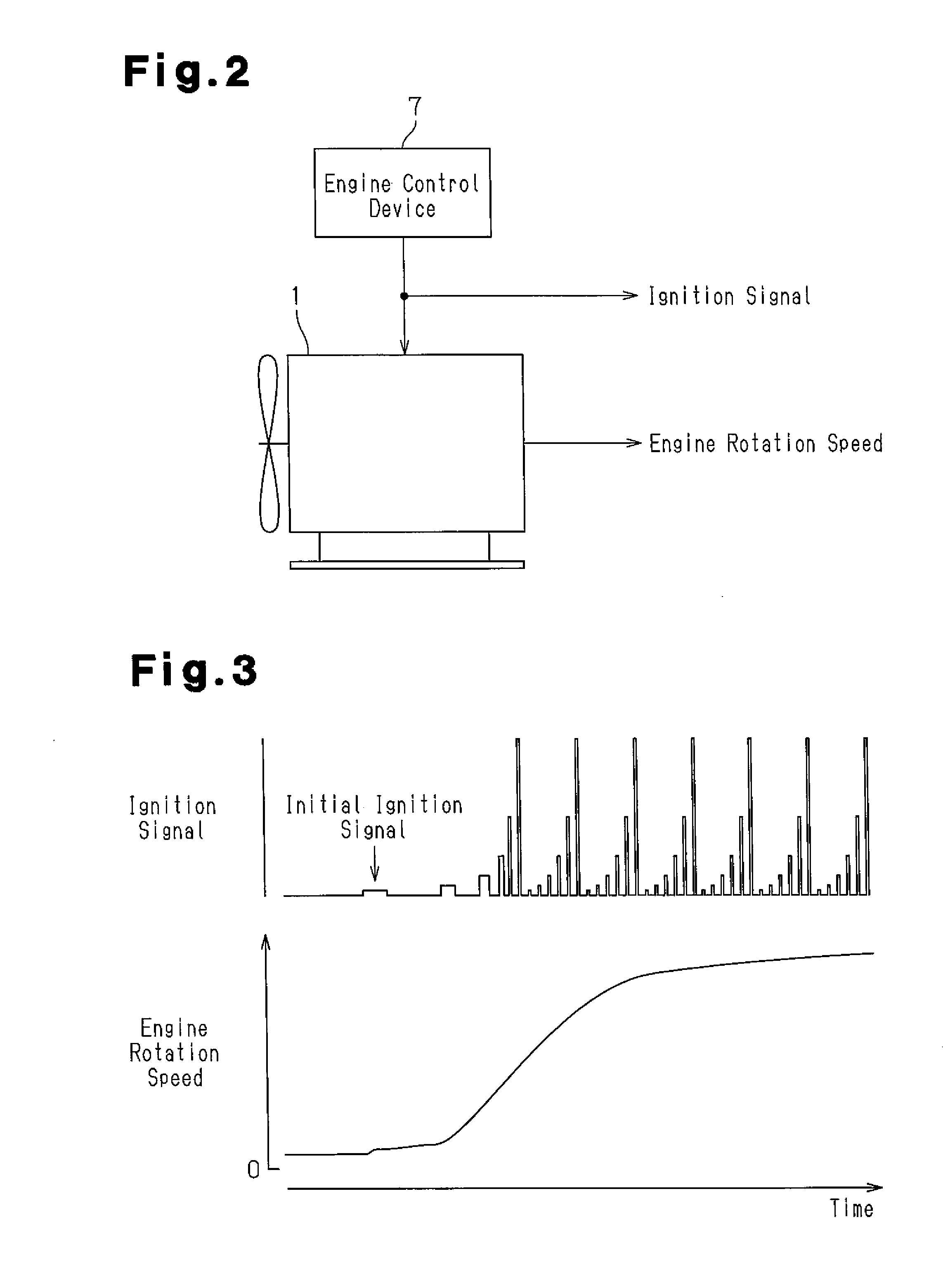
[0023]The engine under test 1 is controlled by an engine control device 7. Further, the ...


PUM


Abstract

An engine testing apparatus is provided with a memory portion for storing a control command value obtained when the rotation speed of a dynamometer is changed by the control command value in accordance with the change of the engine rotation speed in a real vehicle in a period in which the engine behavior in a real vehicle is reproduced without connecting the dynamometer to an engine under test. The engine testing apparatus is provided with an output portion that supplies the control command value stored in the memory portion to the dynamometer with reference to an engine output signal showing the start of the reproducing period.

Description

CROSS REFERENCE TO RELATED APPLICATION[0001]This is a national phase application based on the PCT International Patent Application No. PCT / JP2012 / 056394, filed on Mar. 13, 2012, and claims priority to Japanese Patent Application No. 2011-059603, filed on Mar. 17, 2011, all of which are hereby incorporated by reference in their entireties.FIELD OF THE INVENTION[0002]The present invention relates to an engine testing apparatus provided with a dynamometer connected to an engine under test, and an engine testing method performed by connecting a dynamometer with an engine under test.BACKGROUND OF THE INVENTION[0003]A conventional testing apparatus used to verify the performance of a vehicle engine is provided with a dynamometer 52 connected to an output shaft of an engine under test 50 as an object to be tested via a coupling 51 as shown in FIG. 9. In this type of the testing apparatus, working load evaluation of the engine under test 50 is performed by reproducing the inertia equivalent...

Claims


Application Information

Patent Timeline
Patent Type & Authority Applications(United States)
IPC IPC(8): G01M15/02
CPCG01M15/02G01L3/02G01M15/05G01M17/007G01M17/0072
Inventor SUZUKI, YASUAKIKUSAKABE, TAKUYAHAYASAKA, MASATOSATO, YOSHINAOASAKURA, NOBUHIKOSHIMIZU, SOUSAWADA, YOSHIMASAAKIYAMA, TAKAONAGAO, SHINYAKIDO, YOSHIHARU
Owner TOYOTA JIDOSHA KK
Why Eureka
Try Eureka