Lighting device

Inactive Publication Date: 2014-01-30
AECO LIFE CO
View PDF6 Cites 1 Cited by
  • Summary
  • Abstract
  • Description
  • Claims
  • Application Information

AI Technical Summary

Benefits of technology

[0005]An object of the invention is to provide a lighting device whi

Problems solved by technology

Such a control manner is too tame or draggy for ornamental lighting devices.
On the other hand, convention

Method used


Image

  • Lighting device
  • Lighting device
  • Lighting device

Examples


Example

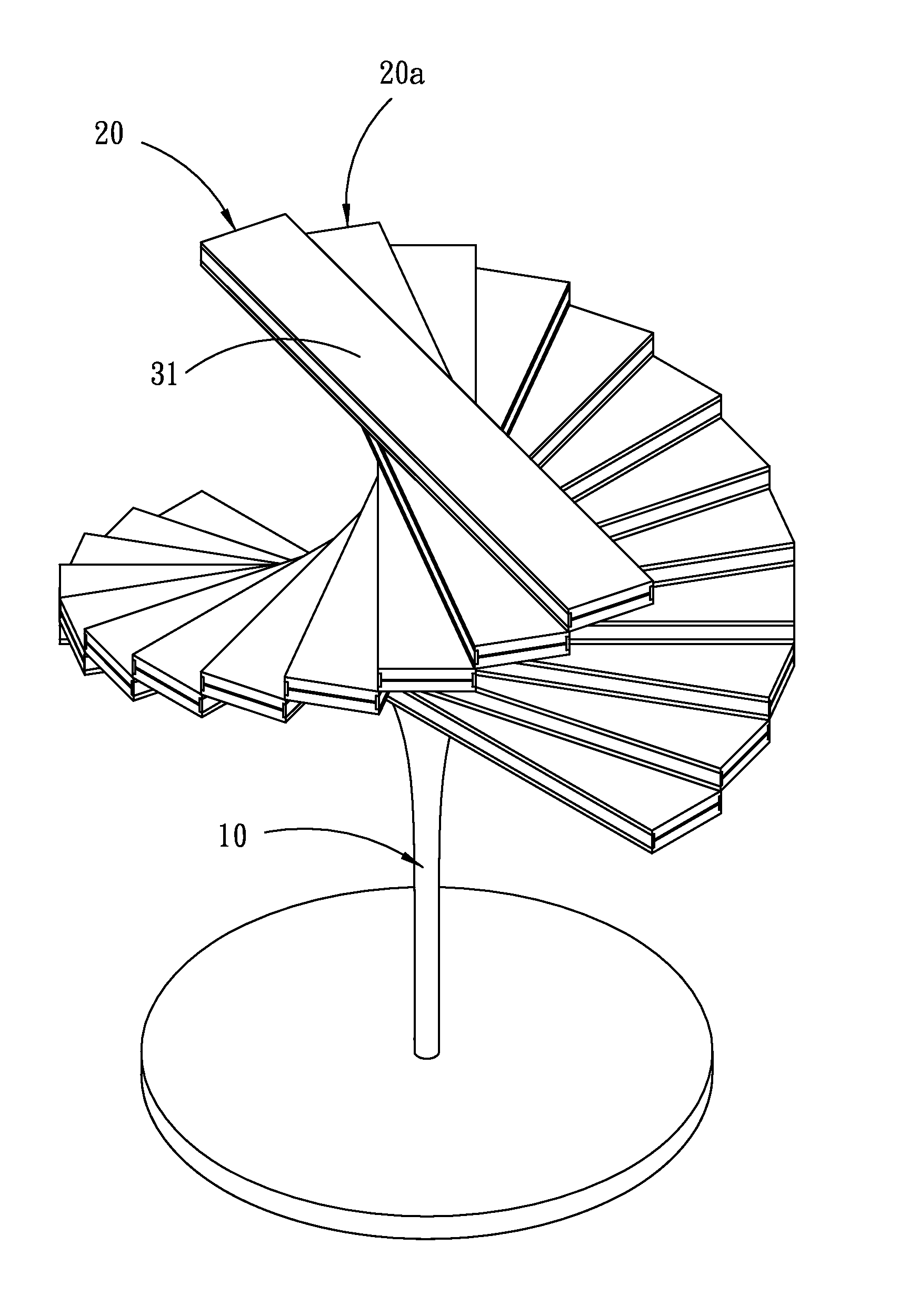
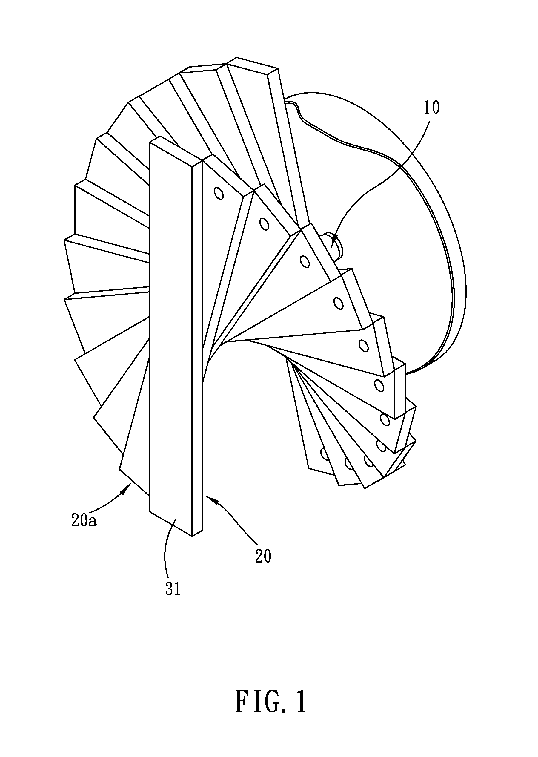
[0015]Please refer to FIG. 1. The lighting device of the invention includes a rod 10 and at least two lighting units 20, 20a. The rod 10 has a wire (not shown) for connecting electric power source. The lighting units 20, 20a superimpose each other and turn about the rod 10 between a first position (as shown in FIG. 6) and a second position (as shown in FIG. 1) to form a shape-variable lighting device.

[0016]In an embodiment of the invention, the first position means the lighting units 20, 20a align with each other (i.e., in a status of complete superposition) and the second position means the lighting units 20, 20a do not align with each other (in a status of incomplete superposition).

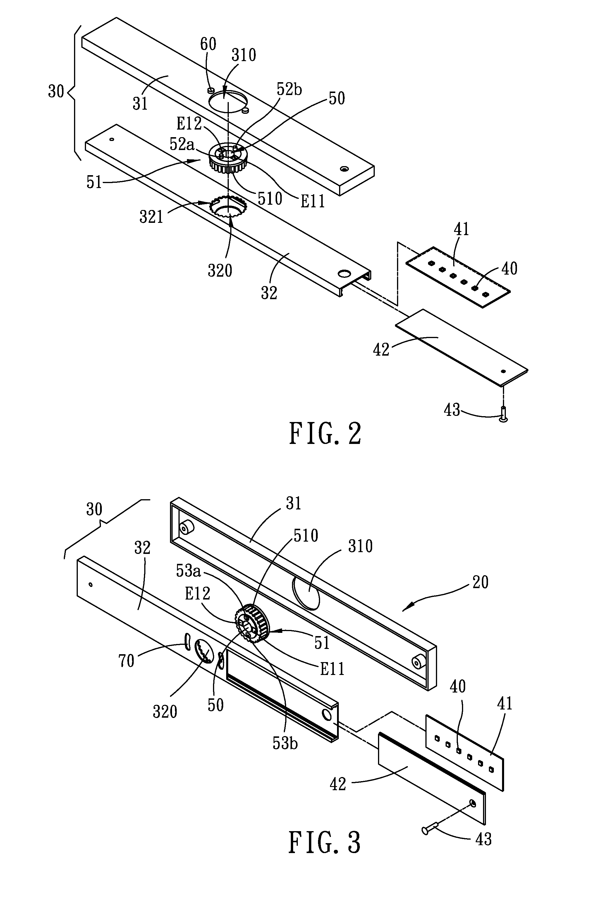
[0017]As shown in FIG. 5, each of the lighting units 20, 20a includes a housing 30 and a lighting element 40. The housing 30 has a through hole 50, a first conductive element E11, a second conductive element E12 and a positioning mechanism.

[0018]Please refer to FIG. 2. The lighting element 40 is mounted...


PUM


Abstract

The lighting device includes a rod and two or more lighting units superimposing each other. Each of the lighting units includes a housing and a lighting element. The housing has a through hole, a first conductive element, a second conductive element and a positioning mechanism. The through hole is penetrated by the rod so that the housing can turn about the rod. The positioning mechanism limits the lighting units to turn between a first position and a second position. The first conductive elements and second conductive elements of the lighting units make contact at the second position, respectively.

Description

BACKGROUND OF THE INVENTION[0001]1. Technical Field[0002]The invention relates to lighting devices, particularly to variable lighting devices.[0003]2. Related Art[0004]Lighting devices are necessary in our daily life. A lighting device serves as not only an illuminator but also ornamentation. Most lighting devices are turned on / off by a switch. Such a control manner is too tame or draggy for ornamental lighting devices. On the other hand, conventional lighting devices are unvarying in shape. For ornamental lighting devices, this is not good enough, too.SUMMARY OF THE INVENTION[0005]An object of the invention is to provide a lighting device which can change in shape and can be turned on / off by the shape change.[0006]To achieve the above object, the lighting device of the invention includes a rod and two or more lighting units superimposing each other. Each of the lighting units includes a housing having a through hole, a first conductive element, a second conductive element and a pos...

Claims


Application Information

Patent Timeline
IPC IPC(8): F21V33/00
CPCF21S6/002F21V21/26F21Y2115/10
Inventor CHU, WEI-CHENGCHOU, EDENCHENG, FU-TINGNI, KUAN-CHUNHO, CHUNG-TONG
Owner AECO LIFE CO
Why Eureka
Try Eureka