

Beam scanning-type display device, method, program and integrated circuit
- Summary
- Abstract
- Description
- Claims
- Application Information
AI Technical Summary
Benefits of technology
Problems solved by technology
Method used
Image

Examples
embodiment 1
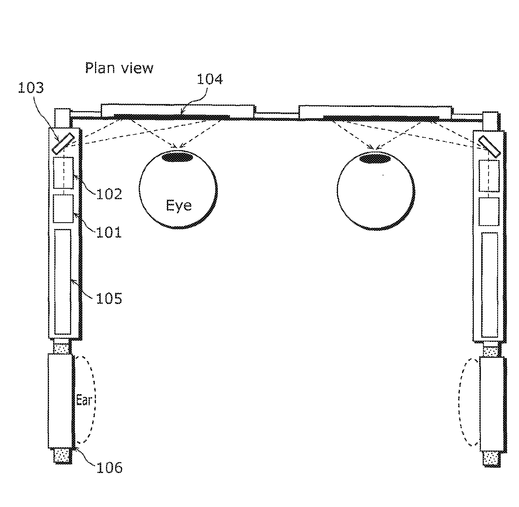
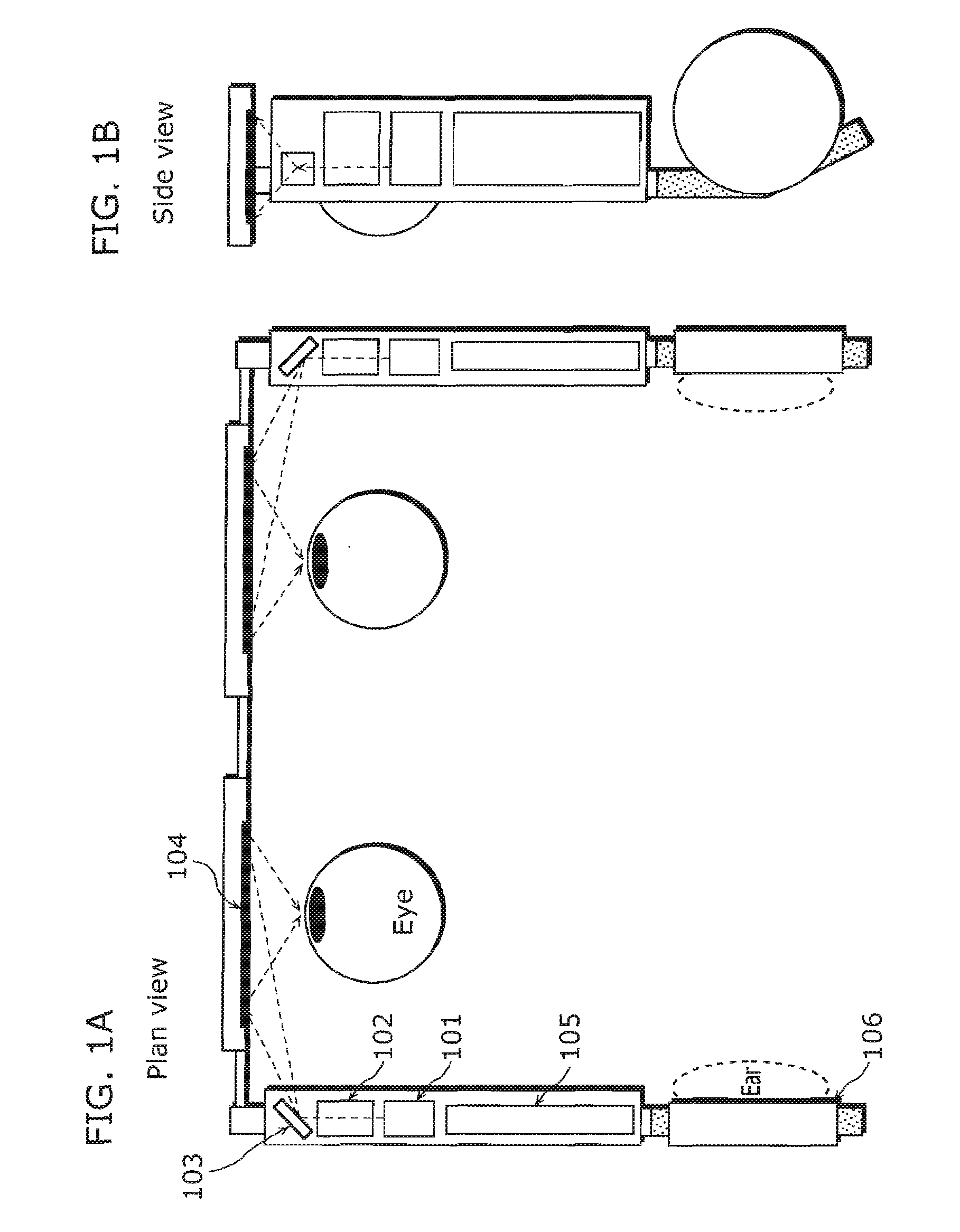
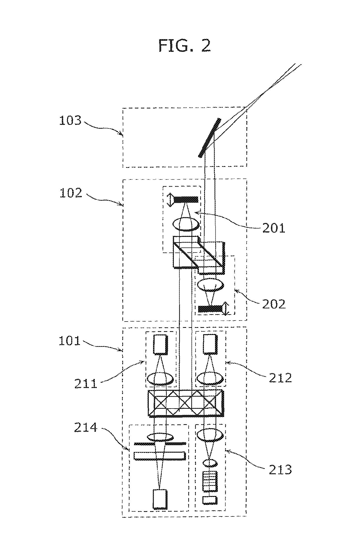
[0275]With reference to FIG. 1A to FIG. 9B, a beam scanning display device of Embodiment 1 according to the present invention is described. FIGS. 1A is a structural diagram (a plan view) of an eyeglass-type head-mounted display (HMD) in Embodiment 1 according to the present invention, and 1B is a structural diagram (a side view) of the same. FIG. 2 is a diagram showing some parts of FIG. 1A in detail. Each of FIG. 3 to FIG. 5 is a diagram illustrating the shape and a function of a cylindrical lens. Each of FIG. 6 and FIG. 7 is a diagram illustrating a function of a wavefront shape changing unit. FIG. 8 is a diagram showing the structure of a scanning unit. Each of FIGS. 9A and 9B is a control block diagram of the HMD.
[0276]As shown in FIGS. 1A and 1B and FIG. 2, the beam scanning-type display device has frame parts in each of which a light source 101, a wavefront shape changing unit 102, a scanning unit 103, a control unit 105, and a headphone unit 106 are arranged, and has lenses i...
embodiment 2
[0358]Next, a description is given of the beam scanning-type display device of Embodiment 2 according to the present invention. The structure of the device is the same as in Embodiment 1, and thus detailed description for the same parts are omitted in the following descriptions given with reference to FIG. 1A to FIG. 9A.
[0359]The light source 101 emits a beam. As shown in FIG. 2, the beam to be outputted is a laser light obtainable by synthesizing the laser lights respectively emitted from the red laser light source 211, the blue laser light source 212, and the green laser light source 213. A proper modulation of the outputs from the respective laser light sources makes it possible to output a laser light having an arbitrary color. Further, modulation implemented by causing a wavefront shape converting unit 102 and a scanning unit 103 to cooperate with each other makes it possible to form an image on a retina of a user.
[0360]In FIG. 2, the green laser light source 213 which emits a ...
embodiment 3
[0427]FIG. 18 shows a schematic structural diagram of an image display device 10 of Embodiment 3 according to the present invention.
[0428]The image display device 10 of Embodiment 3 includes a light source 11, a scanning unit 13 which performs scanning using a laser light 12 emitted from the light source 11, and a deflecting unit 16 which deflects and guides the scanning light 14 from the scanning unit 13 toward the pupil 15 of an observer. A part of the scanning light 14 is reflected as a reflected light 17b from a reflection body 17a. The image display device 10 includes a light detector 18 which detects a spot size 17c of the reflected light 17b and a beam shape adjusting unit 20a which controls the spot size 19b on a retina of the observer at a predefined value or less by changing the beam shape 14c of the scanning light 14 based on the output signal from the light detecting unit 18. In this way, the image display device 10 of Embodiment 3 projects a video on the retina 19a of t...
PUM
 Abstract
Description
Claims
Application Information